
Measuring device and method for optical performance of diffractive optical element

A diffractive optical element and optical performance technology, applied in the field of microlithography, can solve the problem of inaccurate diffraction efficiency, inability to simultaneously measure the energy utilization rate of diffractive optical elements, zero-order diffraction efficiency, high-order diffraction efficiency, and inability to diffract the optical performance of optical elements. Evaluation and other issues to achieve accurate and reliable measurement results

Active Publication Date: 2014-10-01
BEIJING GUOWANG OPTICAL TECH CO LTD
View PDF5 Cites 2 Cited by
  • Summary
  • Abstract
  • Description
  • Claims
  • Application Information

AI Technical Summary

Problems solved by technology

This technology changes the distance between the CCD and the diffractive optical element through the distance changing part to realize the intensity distribution measurement in the direction of the optical axis and the in-plane intensity distribution measurement perpendicular to the optical axis, but it cannot measure the energy utilization rate and zero-order of the diffractive optical element at the same time. Diffraction efficiency, high-order diffraction efficiency and other important indicators, so this technology cannot comprehensively evaluate the optical performance of diffractive optical elements
In addition, when the intensity of the zero-order diffraction spot is too large and the intensity ratio on the diffraction pattern is too large, the diffraction efficiency calculated by the image processing method is inaccurate, so it is necessary to adopt a certain method to directly monitor the energy

Method used

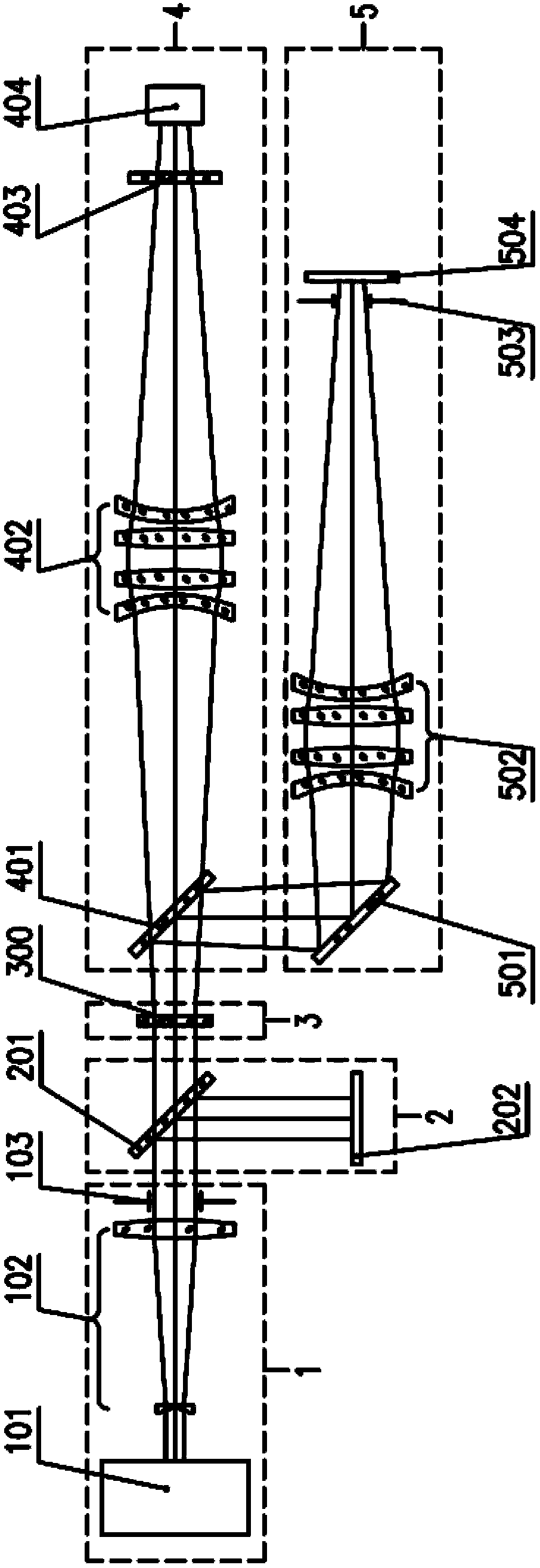
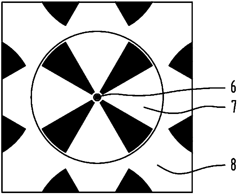

Image

  • Measuring device and method for optical performance of diffractive optical element
  • Measuring device and method for optical performance of diffractive optical element
  • Measuring device and method for optical performance of diffractive optical element

Examples


specific Embodiment

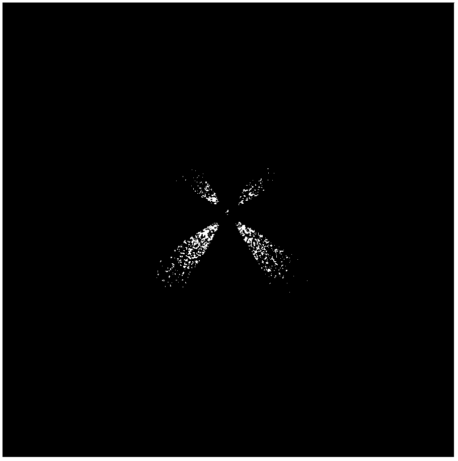
[0076] see figure 2 ,in figure 2 for the use figure 1 The diffraction pattern of a diffractive optical element that produces a quadrupole illumination mode measured by the shown diffractive optical element measuring device has a zero-order bright spot in the center and a high-order diffraction pattern at the edge. Measurements are performed in a dark room.

[0077] The wavelength of the light output by the excimer laser 101 is 193nm, and the size of the outgoing beam is 3mm×3mm; the beam expansion magnification of the beam expander 102 is 10×, and the beam size of the incident beam after the beam expander 102 is expanded is 30mm×30mm; The aperture of the diaphragm 103 is 24 mm×24 mm, and the size of the light beam incident on the diffractive optical element 300 to be tested is 24 mm×24 mm.

[0078] The focal length f and the clear aperture D of the first Fourier transform lens 402 are respectively determined by formula (1) and formula (2). The size of the sensitive surf...


PUM


Abstract

The invention discloses a measurement device and a measurement method for the optical performance of a diffractive optical element for a projection lithography lighting system. The measurement device comprises a lightning unit, an energy monitoring unit, a diffractive optical element fixing bracket, a diffraction pattern measurement unit and an energy utilization rate measurement unit. The optical performance of the diffractive optical element can be evaluated accurately by measuring a diffraction pattern generated by the diffractive optical element and the energy distribution of diffraction spots at all levels. By using the measurement device and the measurement method, not only can the far-field diffraction pattern generated by the diffractive optical element be measured directly, but also the measurement of the energy utilization rate, the zero-order diffraction efficiency and the high-order diffraction efficiency of the diffractive optical element to be measured can be realized. The measurement device is simple in structure, convenient to operate, and accurate and reliable in measurement results.

Description

technical field [0001] The invention relates to the field of microlithography, in particular to a measuring device and a measuring method for the optical properties of diffractive optical elements (Diffractive Optical Elements), in particular to a diffraction method for generating off-axis illumination modes in a projection lithography illumination system An optical property measuring device and a measuring method of an optical element. Background technique [0002] Projection lithography machine is a kind of large-scale integrated circuit manufacturing equipment with the most intensive technology and the highest precision requirements today. It is the lighting technology to obtain various complex pupil light intensity distribution and extremely high light intensity uniformity and the optical imaging technology with close to zero aberration. its core technology. In order to meet the requirements of continuously reducing the feature size of lithography patterns and realizing...

Claims


Application Information

Patent Timeline
Patent Type & Authority Patents(China)
IPC IPC(8): G01M11/02
Inventor 胡中华朱菁杨宝喜肖艳芬彭雪峰陈明曾爱军黄惠杰
Owner BEIJING GUOWANG OPTICAL TECH CO LTD
Learn More