Position pointer

An indicator and position detection technology, which is applied in the direction of instruments, electrical digital data processing, and digital data processing components, etc., can solve the problems of battery replacement frequency impact, power consumption, etc., and achieve power saving and suppression of power consumption.

Active Publication Date: 2012-10-17
WACOM CO LTD
View PDF6 Cites 27 Cited by
  • Summary
  • Abstract
  • Description
  • Claims
  • Application Information

AI Technical Summary

Problems solved by technology

Therefore, when the power switch is turned on, even if the position indicator is not operating on the position detection sensor, that is, when it is not in the state of being used with the position detection sensor, the power supply voltage is always supplied from the battery to each part, and there is power consumption. The problem
[0011] Useful power consumption can be suppressed to a certain extent by frequently turning on / off the power switch according to the use status of the position indicator. However, at this time, the power switch must be frequently operated. The frequency of replacement has an impact on

Method used


Image

  • Position pointer
  • Position pointer
  • Position pointer

Examples


no. 1 Embodiment approach

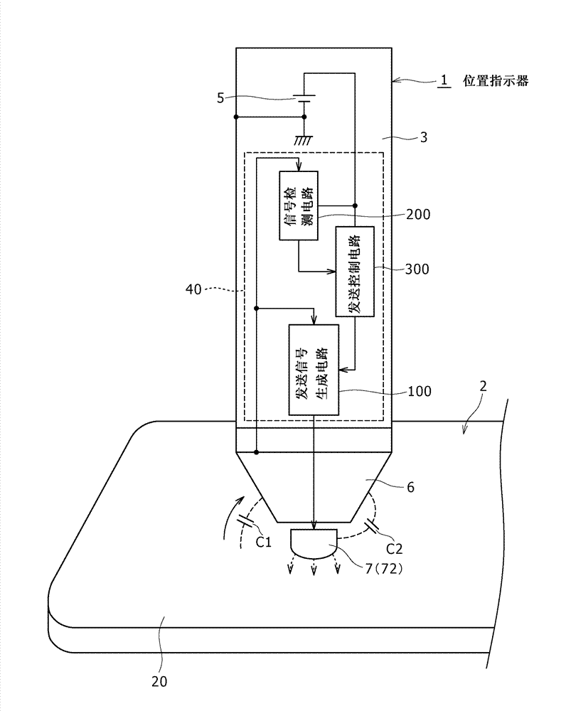
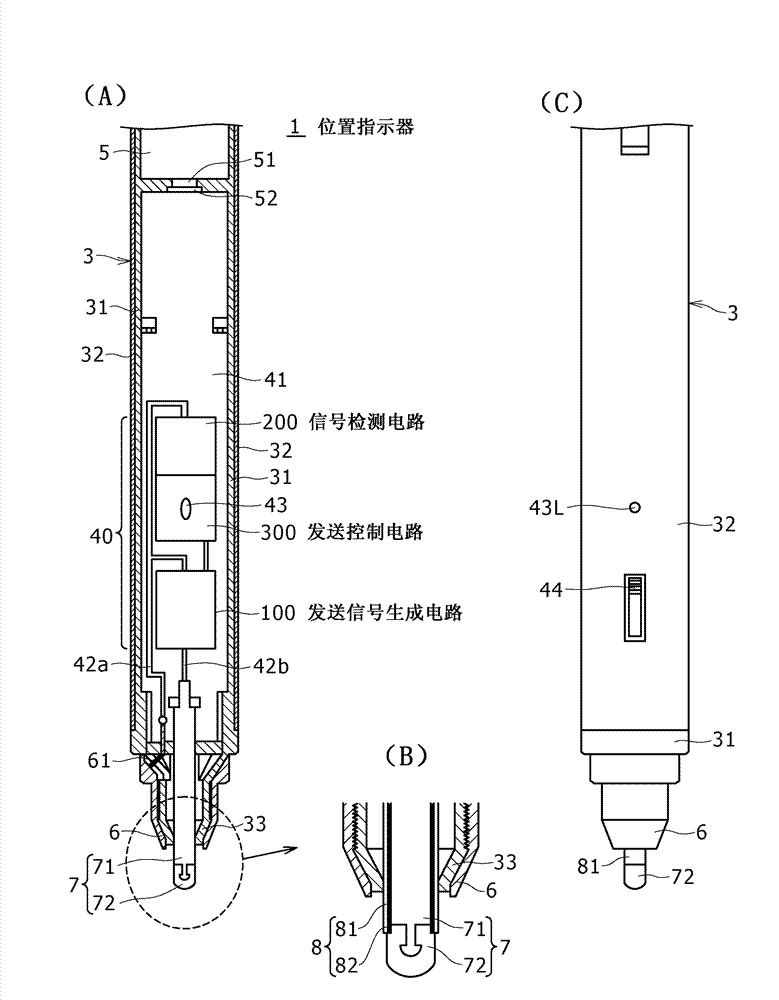
[0031] Hereinafter, embodiments of the position indicator of the present invention will be described with reference to the drawings. figure 1 It is a diagram for briefly explaining the conceptual configuration and processing operation of the position indicator 1 according to the first embodiment of the present invention, and shows a state where the position indicator 1 is located on the board surface of the electrostatic capacitance type position detection sensor 2 picture. also, figure 2 It is a figure for explaining the detailed structure example of the position indicator 1, figure 2 (A) is a partial longitudinal sectional view of the position indicator 1, figure 2 (B) is figure 2 Partial enlarged view of (A), figure 2 (C) is a diagram showing part of the appearance of the position indicator 1 . In the present embodiment, the position indicator 1 is formed in the shape of a stylus having a rod-like appearance.

[0032] The position indicator 1 of the present embod...

no. 2 Embodiment approach

[0103] In the first embodiment described above, the signal detection circuit 200 detects the AC signal received from the position detection sensor 2 via the peripheral electrode 6 via the connection terminal 401 . Therefore, although a detailed circuit example is omitted, the pulse generation circuit 201 of the signal detection circuit 200 needs to provide the same sense amplifier as the primary sense amplifier 101 of the transmission signal generation circuit 100, and the structure may be complicated.

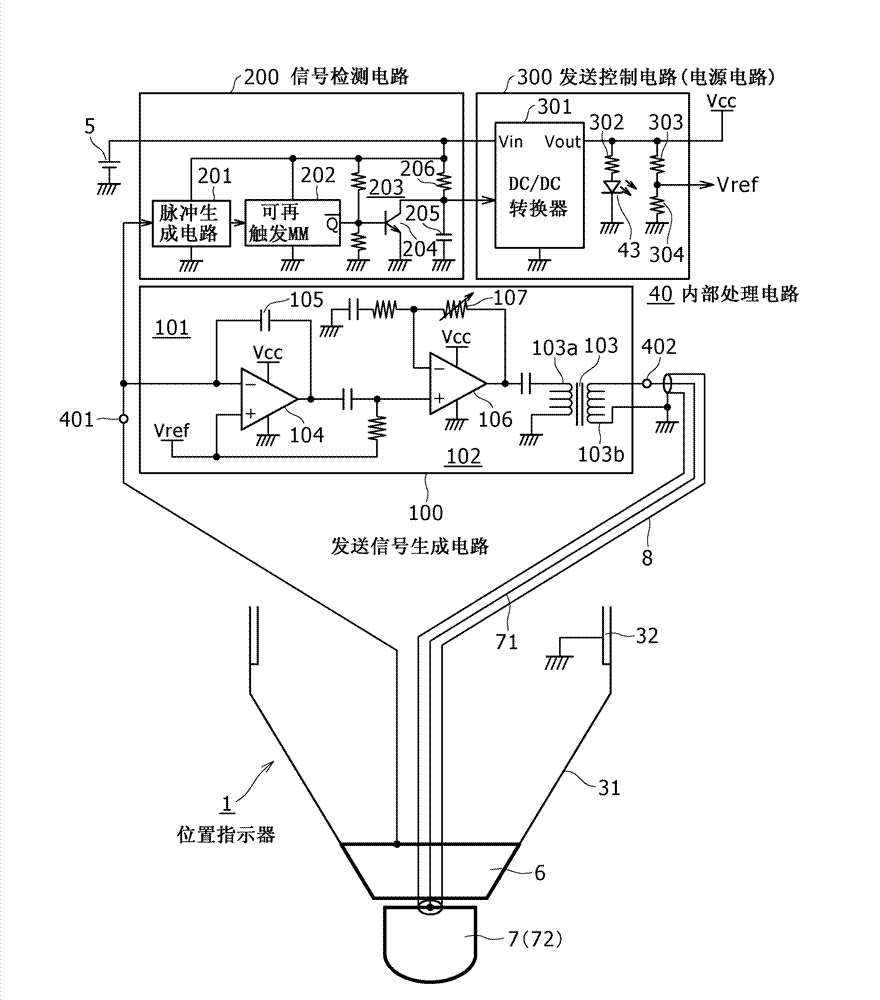
[0104] The second embodiment is an example in which the configuration of the signal detection circuit 200 of the position indicator 1 can be further simplified. Figure 5 A circuit example of the internal processing circuit 400 of the position indicator 1A in the second embodiment is shown. in the Figure 5 in, for with image 3 The same parts as the internal processing circuit 40 of the position indicator 1 according to the first embodiment shown are denoted by the same ref...

no. 3 Embodiment approach

[0127] In the first and second embodiments described above, the position indicators 1 and 1A include the battery 5 as a driving power source. Therefore, when the battery 5 is exhausted, it must be replaced, which is troublesome. In addition, if the battery 5 is built in, the weight of the position indicator increases, and operability may be impaired. The third embodiment is an example in which the above-mentioned problems are solved by using an electric storage circuit including a capacitor instead of a battery.

[0128] Figure 6 It is a circuit diagram showing an example of the internal processing circuit 410 of the position indicator 1B according to the third embodiment, and includes the transmission signal generation circuit 100 , the signal detection circuit 220 and the transmission control circuit 310 . The transmission signal generation circuit 100 has the same configuration as the internal processing circuit 40 of the first embodiment. In addition, the structural st...


PUM


Abstract

A position pointer is provided for use with a position detection sensor, capable of achieving power saving. The position pointer includes: a first electrode configured to receive an AC signal from a position detection sensor; a transmission signal production circuit configured to produce a position signal, based on which the position detection sensor detects a position of the position pointer; a second electrode different from the first electrode and configured to transmit the position signal to the position detection sensor; a signal detection circuit configured to detect whether or not the AC signal from the position detection sensor is received through the first electrode; and a transmission controlling circuit configured to control transmission of the position signal through the second electrode to the position detection sensor in response to an output from the signal detection circuit. Corresponding to the situation of detecting an AC signal received by the first electrode and coming from the position detection sensor, the second electrode sends a signal used for the position detection sensor to detect position.

Description

technical field [0001] The present invention relates to a position indicator for use with a position detection sensor. Background technique [0002] Conventionally, various position indicators for use with position detection sensors have been proposed. For example, Patent Document 1 (Japanese Patent Laid-Open No. 7-295722 ) and Patent Document 2 (Japanese Patent Laid-Open No. 8-272509 ) disclose coordinate input devices that include an AC signal generator in a position indicator and include The position detection sensor detects the position of the position indicator by detecting a signal corresponding to an AC signal sent from the position indicator by a battery as a driving power thereof. [0003] In addition, Patent Document 3 (Japanese Unexamined Patent Application Publication No. 2007-183809) discloses a position indicator that includes a switch circuit for switching between signal reception and signal transmission to the conductor of the pen tip, and includes a so-call...

Claims


Application Information

Patent Timeline
Patent Type & Authority Applications(China)
IPC IPC(8): G06F3/033G06F3/041
CPCG06F3/041G06F1/3262G06F3/03545G06F3/0442G06F3/0446G06F3/0445G06F3/0441G06F3/038G06F3/046G06F3/0383
Inventor 小田康雄八木正树杉山义久
Owner WACOM CO LTD
Why Eureka
Try Eureka