Dimmable LED (Light-Emitting Diode) driving circuit and driving method

A LED drive and circuit technology, applied in the field of power electronics, can solve problems such as SCR cannot maintain conduction, SCR current is uncontrollable, LED flickering, etc., to ensure brightness, wide dimming range, and solve flickering problems Effect

Active Publication Date: 2012-10-17
SILERGY SEMICON TECH (HANGZHOU) CO LTD
View PDF4 Cites 51 Cited by
  • Summary
  • Abstract
  • Description
  • Claims
  • Application Information

AI Technical Summary

Problems solved by technology

However, the existing LED drive circuit generally contains a large filter capacitor, so that the LC resonance in the circuit will make the current through the thyristor uncontrollable, resulting in the thyristor not being able to maintain conduction, so the LED will flicker
In recent years, a variety of control schemes for LED dimming using thyristors have also been proposed. For example, the problem of uncontrollable current can be solved by adding a dummy load (such as a resistor), but the power consumption of the increased dummy load Undoubtedly, the efficiency of the whole machine will be low

Method used


Image

  • Dimmable LED (Light-Emitting Diode) driving circuit and driving method
  • Dimmable LED (Light-Emitting Diode) driving circuit and driving method
  • Dimmable LED (Light-Emitting Diode) driving circuit and driving method

Examples


Embodiment 1

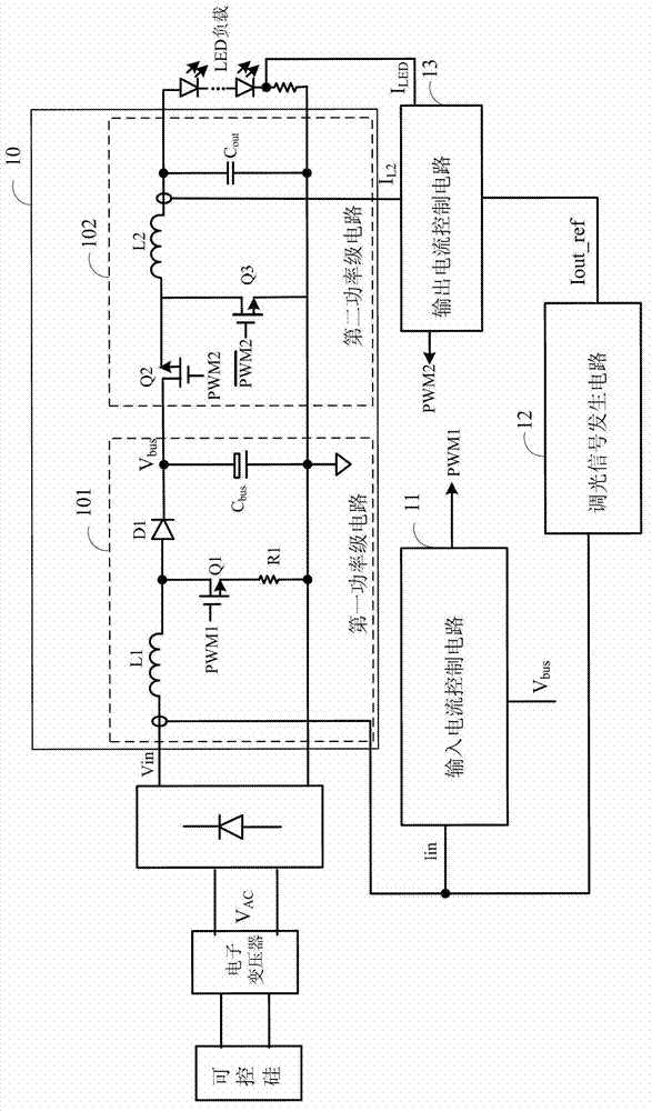
[0070] according to figure 1 , shows the circuit diagram of the first embodiment of a dimmable LED driving circuit according to the present invention. It inputs the AC voltage of the power grid to the rectifier bridge after being processed by a thyristor rectifier circuit Triac and an electronic transformer to obtain a DC voltage signal V in , a power stage circuit receives the DC voltage signal V in And output a constant current to drive the LED load. Such as figure 1 As shown, the power stage circuit 10 includes a first power stage circuit 101 and a second power stage circuit 102. In this embodiment, the first power stage circuit 101 is preferably a first stage Boost circuit, including: an inductor L 1 , Diode D 1 , switch tube Q 1 and the output capacitor C bus ; The second power stage circuit is preferably a second stage Buck circuit, including: an inductance L 2 , switch tube Q 2 , switch tube Q 3 and output capacitor C out , the first stage Boost circuit receiv...

Embodiment 2

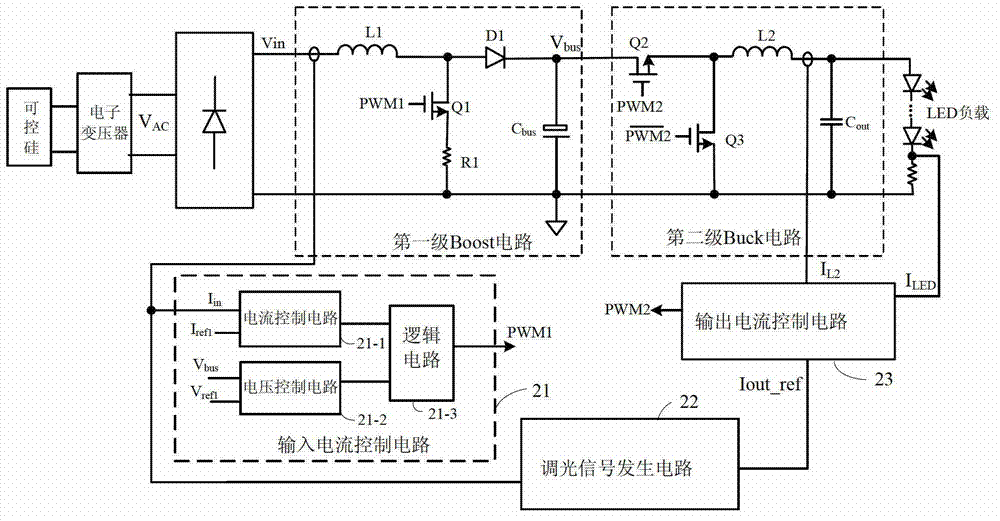
[0077] refer to figure 2 , is shown as a circuit diagram of a second embodiment of a dimmable LED driving circuit according to the present invention. This embodiment specifically describes the circuit structure and working process of the input current control circuit.

[0078] Such as figure 2 As shown, the input current control circuit 21 further includes a current control circuit 21-1, a voltage control circuit 21-2 and a logic circuit 21-3, wherein the current control circuit 21-1 receives the input current I in and a first reference current I ref1 , and generate a current control signal V ct1 , where the first reference current I ref1 Corresponding to the peak value of the square wave signal representing the input current; the voltage control circuit 21-2 receives the first output voltage V bus and the first reference voltage V ref1 , and generate a voltage control signal V ct2 ; The logic circuit 21-3 receives the current control signal V ct1 and the voltage cont...

Embodiment 3

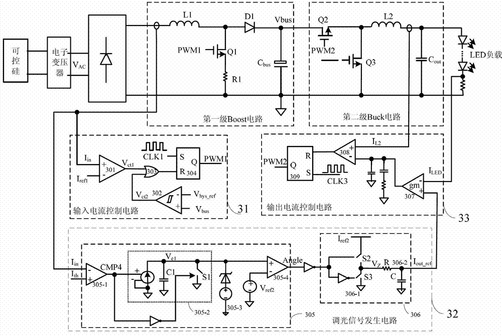
[0101] refer to Figure 6 , is shown as a circuit diagram of a third embodiment of a dimmable LED drive circuit according to the present invention; this embodiment is the same as the dimming signal generation circuit and output current control circuit in the third embodiment above, here Without repeating the description, the difference is that the implementation of the input current control circuit in this embodiment is different from that in the second embodiment, that is, Figure 6 The input current control circuit in 61 and image 3 The input current control circuit 31 is different, but Figure 6 in the dimming signal generation circuit 62 and image 3 The dimming signal generation circuit 32 in the same, the output current control circuit 63 and image 3 The output current control circuit 33 is the same, and a specific implementation and working principle of the input current control circuit in this embodiment will be introduced in detail below.

[0102] Such as Figu...


PUM


Abstract

The invention provides a dimmable LED (Light-Emitting Diode) driving circuit and a driving method. An input current in a first power-level circuit is controlled as a square wave signal within a rectifier conducting time interval by an input current control circuit, the peak value of the input current is a constant value and meets the requirement of the minimum load current of an electronic transformer, and the valley value of the input current is zero; and the input current is kept at zero within a rectifier nonconducting time interval. The load current of the electronic transformer can be kept larger than the minimum load current, and thus, a normal working state can be kept in the working process, and the problem of LED load flicker caused by the switching off of the electronic transformer is avoided; in addition, information on the input current is detected through a dimmable signal generating circuit so that a dimmable signal for representing information on a conduction angle of a rectifier is obtained, an LED load is precisely dimmed, the dimming range is wide, and the dimming effect is good; and finally, constant-current control for the current of the LED load is realized by an output current control circuit, and therefore, the brightness stability of the LED load is ensured.

Description

technical field [0001] The present invention relates to the field of power electronics, more specifically, to a dimmable LED drive circuit and a drive method. Background technique [0002] In the field of lighting, it has become a development trend for LED lamps to replace traditional light sources (such as halogen lamps). In the process of replacing halogen lamps with LED lamps, on the one hand, it needs to match with the electronic transformer in the traditional circuit to ensure the normal operation of the electronic transformer. ; On the other hand, it is necessary to precisely adjust the light of the LED load to maximize the advantages of energy saving and high light efficiency of the LED light load. [0003] In the prior art, the dimming scheme of the thyristor is usually used to dim the LED lamp load. In the LED drive circuit with electronic transformer, the thyristor dimmer is generally placed at the front end of the electronic transformer. The basic principle of th...

Claims


Application Information

Patent Timeline
Patent Type & Authority Applications(China)
IPC IPC(8): H05B37/02H05B44/00
CPCY02B20/347Y02B20/42H05B33/0839H05B45/10Y02B20/30H05B45/38H05B45/375
Inventor 余峰黄晓冬
Owner SILERGY SEMICON TECH (HANGZHOU) CO LTD
Why Eureka
Try Eureka