Method for determining the cut quality of a laser cutting process using a simulation program

A laser cutting, laser cutting machine technology, applied in laser welding equipment, design optimization/simulation, manufacturing tools, etc., can solve problems such as unknown physical reasons and inability to achieve 10μ radiator cutting quality

Inactive Publication Date: 2012-10-17
FRAUNHOFER GESELLSCHAFT ZUR FOERDERUNG DER ANGEWANDTEN FORSCHUNG EV +1
View PDF0 Cites 8 Cited by
  • Summary
  • Abstract
  • Description
  • Claims
  • Application Information

AI Technical Summary

Problems solved by technology

These measures have not been successful so far, so that the cutting quality of 1μ radiators has not yet been achieved by 10μ radiators
Furthermore, the physical reasons that might explain the different cut qualities are not known

Method used


Image

  • Method for determining the cut quality of a laser cutting process using a simulation program
  • Method for determining the cut quality of a laser cutting process using a simulation program
  • Method for determining the cut quality of a laser cutting process using a simulation program

Examples


Embodiment Construction

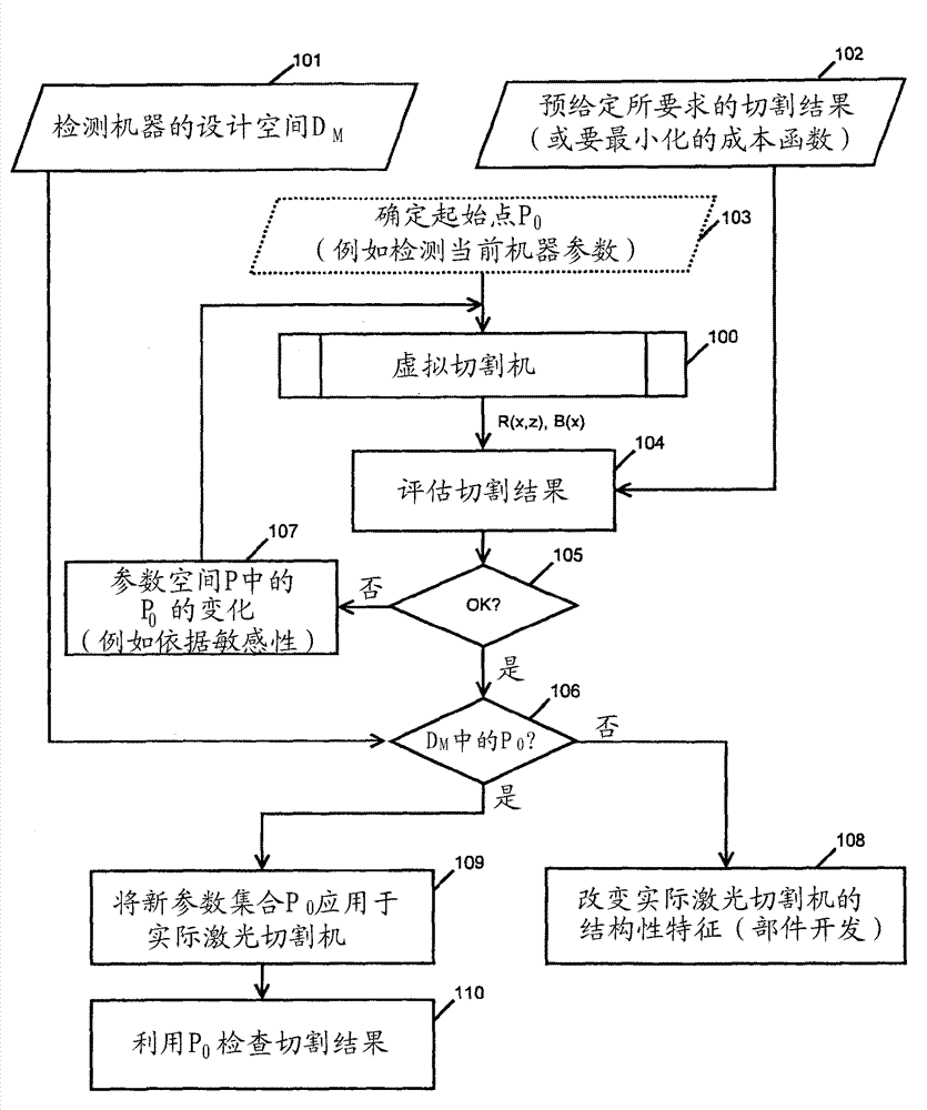
[0132] The method according to the invention (as shown in this figure) uses a virtual cutter, which is identified with the reference numeral 100 . To carry out the method, on the one hand examine (erfassen) the design space D M (step 101), and on the other hand input the required cutting result (step 102). A cost function to be minimized may also be determined in step 102 .

[0133] In order to start the virtual cutting machine 100, a starting point P is determined in step 103 0 , for example, is determined by detecting the machine parameters of the current actual cutting machine. Value P 0 The set of is selected from the parameter space P, as it was further defined before.

[0134] The simulation program is initiated by generating a virtual cut using a virtual cutting machine, which may be based on actual values. The simulation program outputs a cutting result containing the spatial distribution R(x,z) of the ridge amplitude on the cutting surface and the spatial distrib...


PUM


Abstract

The application relates to a method for determining the cut quality of a laser cutting process, said quality being assessed on the basis of the formation of solidification ridges along the cut face and / or burr formation on the lower edge of the cut face. In said method, a virtual laser cutting machine in a simulation program can be virtually operated with a set of values P0 from a parameter space P.; In a step a), the parameter set P0 is entered in the virtual cutting machine (103), then in step b), a cut is made in the virtual workpiece by calculating, from partial differential equations with initial and boundary values, the progression of the melt film thickness over time and the position of the melt front at the apex of the cutting front according to the depth of the cut and the time, and then in step c), the spatial distribution of the ridge amplitude on the cut face is specified by projecting the progression of the absorption front onto the cut face and / or a spatial distribution of the burr is calculated from the progression of the melt film thickness over time and the discharge speed on the lower edge of the cut face, and in step d), a virtual cut quality is provided (104) for further analysis.

Description

technical field [0001] The invention relates to a method for determining the cutting result of a laser cutting process, which is evaluated based on the formation of solidified ridges (Erstarrungsriefe) along the cut surface and / or the formation of burrs on the lower edge of the cut surface, wherein in a simulation A virtual laser cutter is provided in the program, which can be represented by a value P from the parameter space P 0 A collection of virtual operations. Background technique [0002] Laser cutting is an established separation method. Among the laser-assisted manufacturing methods, laser cutting occupies a leading position in industrial applications. From the perspective of the user, high productivity with high quality is required for this manufacturing method. [0003] For laser cutting in the field of macroscopic applications in the plate thickness range of 1 mm to 30 mm, high performance CO 2 laser (10µ radiator), the high-performance CO 2 The laser has a r...

Claims


Application Information

Patent Timeline
Patent Type & Authority Applications(China)
IPC IPC(8): B23K26/06B23K26/38G06F17/50
CPCG06F2217/78G06F2217/80B23K26/38B23K26/06G06F17/5009G06F30/20G06F2119/06G06F2119/08
Inventor W.舒尔茨J.许特勒G.福森M.尼森
Owner FRAUNHOFER GESELLSCHAFT ZUR FOERDERUNG DER ANGEWANDTEN FORSCHUNG EV
Why Eureka
Try Eureka