Method for operating an ignition device for an internal combustion engine, and ignition device for an internal combustion engine for carrying out the method

An ignition device and internal combustion engine technology, which is applied in the direction of engine ignition, other devices, induction energy storage devices, etc., can solve the problems of serial engines that cannot be ignited in key operating states, and wear of ignition plugs, so as to improve ignition safety and ensure reliability The effect of forming and reducing manufacturing costs

Active Publication Date: 2012-10-17
CONTINENTAL AUTOMOTIVE GMBH
View PDF5 Cites 14 Cited by
  • Summary
  • Abstract
  • Description
  • Claims
  • Application Information

AI Technical Summary

Problems solved by technology

[0016] Although ignition with such an alternating voltage can solve the problems of combustion technology, it is only suitable for high-end vehicles for cost reasons
Therefore, hitherto, the wear of the ignition plugs associated with the increased ignition energy had to be accepted, or the ignition-critical operating states could not be achieved on serial engines

Method used


Image

  • Method for operating an ignition device for an internal combustion engine, and ignition device for an internal combustion engine for carrying out the method
  • Method for operating an ignition device for an internal combustion engine, and ignition device for an internal combustion engine for carrying out the method
  • Method for operating an ignition device for an internal combustion engine, and ignition device for an internal combustion engine for carrying out the method

Examples


Embodiment Construction

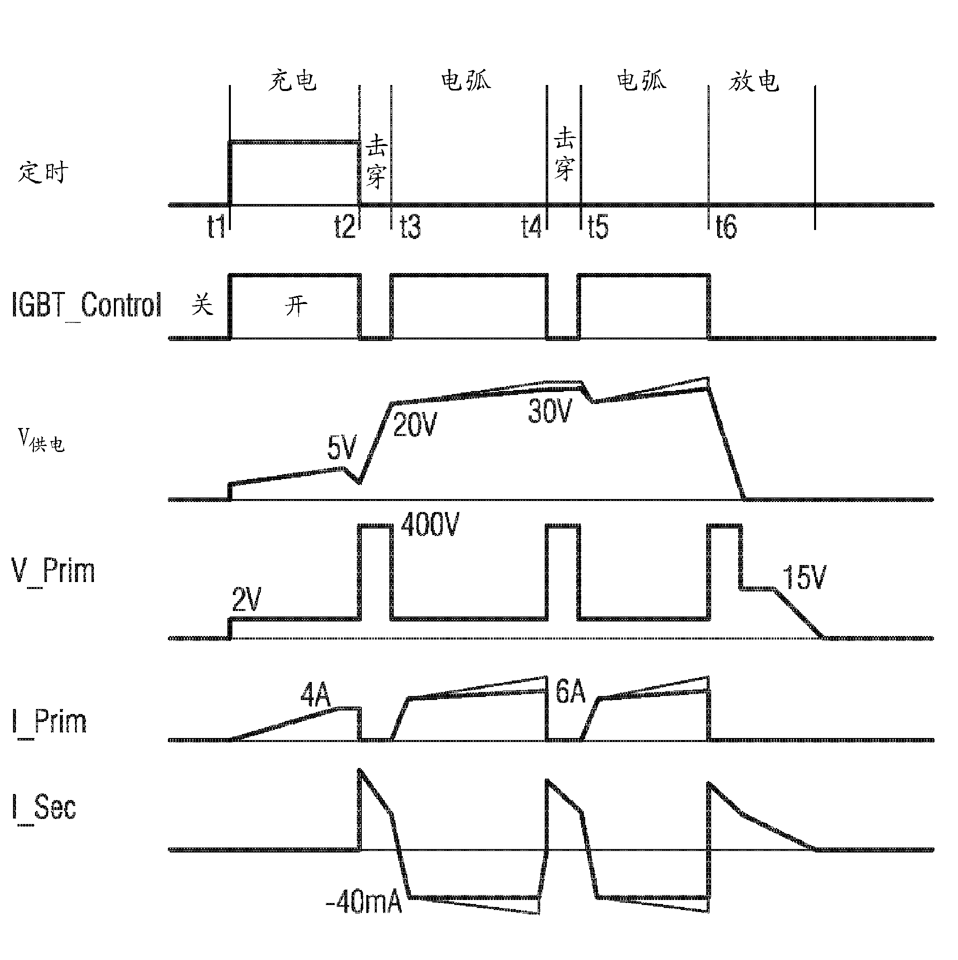
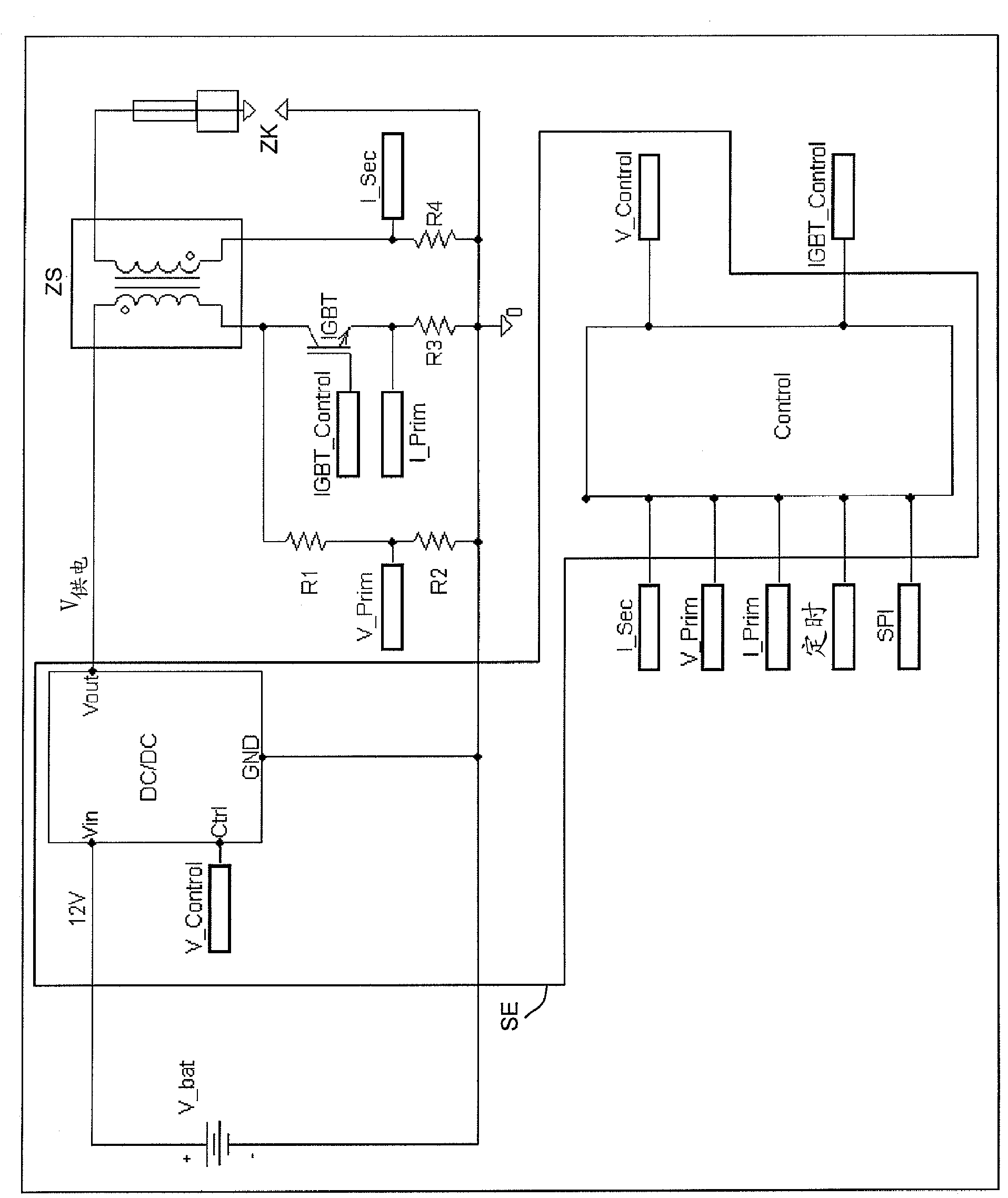
[0037] according to figure 1 The ignition device according to the invention comprises a controllable supply voltage source DC / DC configured as a voltage converter for supplying one or more ignition coils ZS with a variable supply voltage V 供电 . The supply voltage is supplied from the vehicle supply voltage V_bat, which is currently approximately 12V. This supply voltage supplies one or more ignition coils ZS, advantageously no blocking diodes being required anymore. A conventional glow plug ZK can be used, which is connected to the secondary winding of the ignition coil ZS. The primary winding of the ignition coil ZS is connected in series with a switching element, usually designed as an IGBT, for switching the ignition coil ZS. Means are provided for detecting the primary voltage as well as the primary and secondary currents.

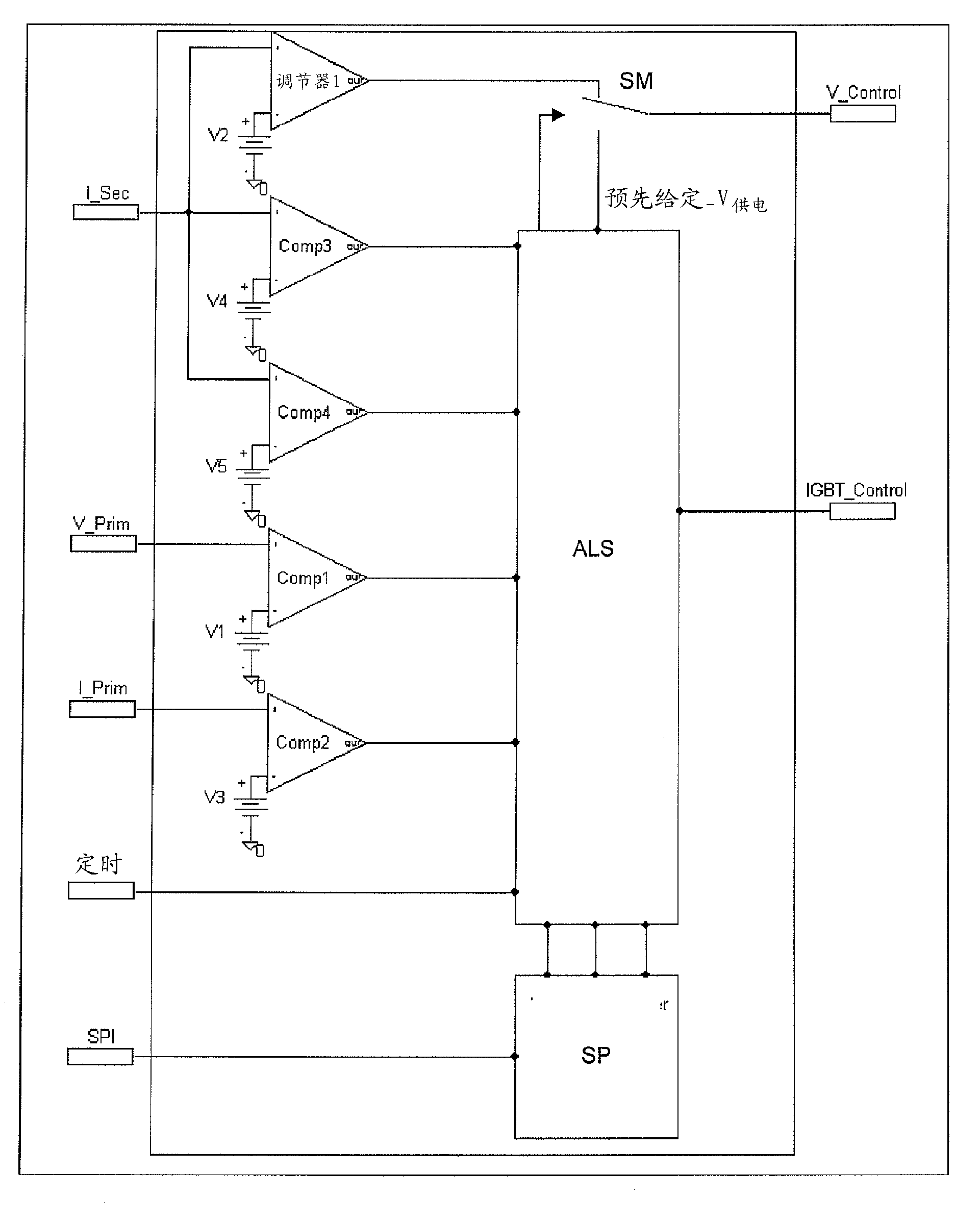
[0038] The control unit SE generates a variable supply voltage V by means of a voltage converter DC / DC depending on the detected operating paramet...


PUM


Abstract

The invention relates to a method for operating an ignition device for an internal combustion engine, which ignition device is formed with an ignition coil (ZS) which is configured as a transformer, a spark plug (ZK) which is connected to the secondary winding of the ignition coil (ZS), an actuable switching element (IGBT) which is connected in series to the primary winding of the ignition coil (ZS), and a control unit (SE) which is connected to the control input of the switching element (IGBT), wherein the control unit (SE) provides an adjustable supply voltage (Vsupply) for the ignition coil (ZS) and an actuating signal (IGBT_Control) for the switching element (IGBT) as a function of the currents (I_Prim, I_Sec) through the primary and the secondary windings of the ignition coil (ZS) and the voltage between the connecting point of the primary winding of the ignition coil (ZS); to the switching element (IGBT) and the negative terminal of the supply voltage (GND), as a result of which firstly operation of the spark plug (ZK) by way of alternating current is possible and secondly regulation of said current is possible, which leads to more reliable ignition with a lower wear of the spark plugs.

Description

Background technique [0001] For many years, series ignition systems, which are now constructed as gasoline engines, operate on the simple and reliable principle of coil discharge, that is to say, the ignition coils, which are correspondingly designed as transformers, draw from the on-board supply voltage on the primary side according to their inductance Charge partially up to its saturation range. At the moment of ignition, charging is interrupted by means of an electronic circuit, for example by ignition of an IGBT (Insulated Gate Bipolar Transistor). A voltage of, for example, 5 kV to 35 kV is thus formed on the secondary side, which voltage leads to arcing in the spark gap of the ignition plug in the combustion chamber of the internal combustion engine. Next, the energy stored in the coil is released in the ignition plasma. [0002] Consumption savings and emissions have to be achieved during the development of propulsion engines, which have consistently led to an increas...

Claims


Application Information

Patent Timeline
Patent Type & Authority Applications(China)
IPC IPC(8): F02P15/10F02P3/04F02P15/08
CPCF02D2041/2003F02D2041/2058F02P3/0442F02P15/08F02P15/10F02P3/04
Inventor S.艾森M.格岑贝格尔A.罗伊特H.施莫斯S.博尔茨
Owner CONTINENTAL AUTOMOTIVE GMBH
Why Eureka
Try Eureka