Disc-shaped aircraft toy
A technology of aircraft and toys, applied in the field of saucer-shaped aircraft toys, can solve the problems of large impact, troublesome control, and unstable flight, etc., and achieve the effects of weight reduction, easy control, and continuity
- Summary
- Abstract
- Description
- Claims
- Application Information
AI Technical Summary
Problems solved by technology
Method used
Image
Examples
Embodiment 1
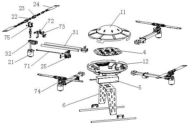
[0023] Such as figure 1 As shown, a saucer-shaped aircraft toy includes a circular body, four groups of rotor power assemblies, a wing frame, a control module 4 arranged on the body, a battery 5, and a remote controller wirelessly connected to the control module 4 (not shown in the figure) out), landing bracket 6. The machine body includes an upper cover 11 and a bottom cover 12 which are engaged with each other; the landing bracket 6 is installed under the bottom cover 12 .
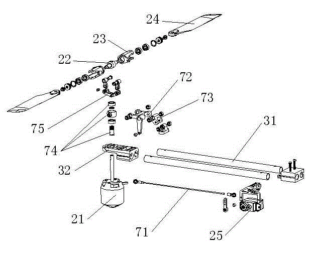
[0024] Such as figure 1 with figure 2 As shown, the wing frame includes a fixed rod 31 and a mounting block 32, wherein one end of the fixed rod 31 is connected to the body, and the mounting block 32 is connected to the other end of the fixed rod 31, and the four groups of wing frames are arranged symmetrically with the center of the body; the rotor power assembly is connected On the mounting block 32.
[0025] Rotor power assembly comprises motor 21, empennage connection block 22, blade clip 23, bl...
Embodiment 2
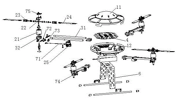
[0031] Such as image 3 As shown, the basic structural form of this embodiment is the same as that of Embodiment 1; the difference is that image 3 with Figure 4 As shown, the motor 21 adopts a motor whose output shaft can rotate and slide relative to the body of the motor, and the motor 21 is fixed on the top of the mounting block 32; The output rod is hinged, the other end is hinged with the crank swing rod 72, the other end of the crank swing rod 72 is hinged with the outer ring of the bearing assembly 74, the bend of the crank swing rod 72 is hinged with one end of the joint rod 73, and the other end of the joint rod 73 One end is hinged on the mounting block 32; the inner ring of the bearing assembly 74 is fixedly connected with the output shaft of the motor 21, the empennage driving rod 75 is fixedly connected with the output shaft of the motor 21, and the empennage driving rod 75 is also connected with the blade clamp 23.
[0032] The working process of the variable ...
PUM
 Abstract
Description
Claims
Application Information
 - R&D
- Intellectual Property
- Life Sciences
- Materials
- Tech Scout
- Unparalleled Data Quality
- Higher Quality Content
- 60% Fewer Hallucinations
Browse by: Latest US Patents, China's latest patents, Technical Efficacy Thesaurus, Application Domain, Technology Topic, Popular Technical Reports.
© 2025 PatSnap. All rights reserved.Legal|Privacy policy|Modern Slavery Act Transparency Statement|Sitemap|About US| Contact US: help@patsnap.com


