Light foot lead welding machine of bulb in bulb

A technology of lamp pin lead wire and bubble in bubble, which is applied in the field of lamp pin lead wire welding machine, which can solve the problems of manual work, unstable welding quality, and prone to industrial accidents, etc., and achieve the effect of improving stability

Inactive Publication Date: 2012-10-24
佛山市南海佛阳照明有限公司
View PDF5 Cites 33 Cited by
  • Summary
  • Abstract
  • Description
  • Claims
  • Application Information

AI Technical Summary

Problems solved by technology

[0007] The welding of the lamp pin leads of the existing bubble-in-the-bulb is performed manually by hand-held lamp cap a and stem b on t

Method used


Image

  • Light foot lead welding machine of bulb in bulb
  • Light foot lead welding machine of bulb in bulb
  • Light foot lead welding machine of bulb in bulb

Examples


Embodiment 1

[0086] Such as Figure 4 and Figure 5 As shown, a welding machine for lamp pin leads of a bulb in a bulb includes a base frame 1, a driving power device arranged on the base frame 1, a tray 11 driven forward by the driving power device, The central controller 121 arranged on the chassis 1 and the clamping device 2 arranged on the tray 11 .

[0087] The driving power device includes a cam splitter 12 and a motor and reduction gear box assembly 123 for driving the cam splitter 12 .

[0088] A separate synchronous output shaft 122 is also arranged on the cam divider 12 of the driving power unit, an angle encoder 124 is connected with the output shaft 122, and the angle encoder 124 is connected with the central controller 121 connect. In this way, the angular displacement of the output shaft 122 and the angular displacement of the pallet 11 have a fixed proportional relationship, and the angle encoder 124 can indirectly sample the angular displacement of the pallet 11, so that...

Embodiment 2

[0137] The difference from Example 1 is:

[0138] 1. The tray 11 is provided with 8 first chucks 21 that can only hold the lamp cap a, while the stem b is transported by the stem manipulator 32 of the stem feeding station 3 but not clamped in the The structure of the first clip 21 on the tray 11 can adopt the structure disclosed in Embodiment 1, or other structures, as long as it can hold the lamp cap a.

[0139] 2. The stem feeding station 3 is set as the lower station of the lamp cap feeding station 4;

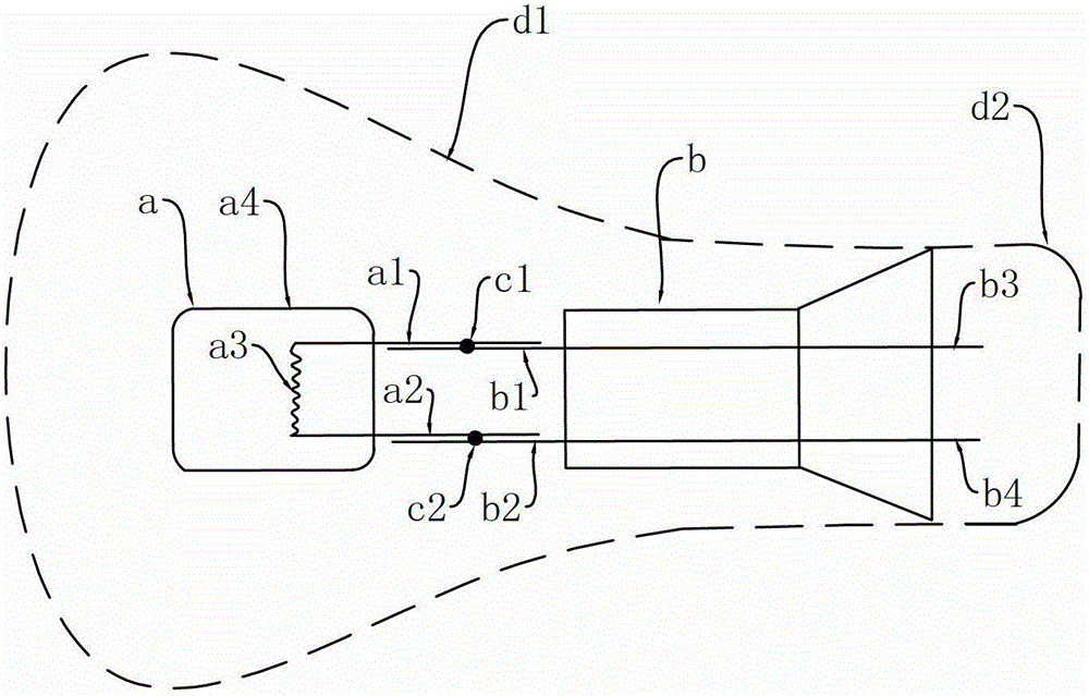
[0140] 3. The stem manipulator 32 of the stem feeding station 3 grabs the stem b from the stem automatic feeder 31 and then sends the stem b to the vicinity of the position of the corresponding first chuck 21 and makes it The lamp pin leads (b1, b2) of the stem b correspond to and partially overlap with the lamp pin leads (a1, a2) of the lamp cap a clamped in the first chuck 21, but the stem manipulator 32 The pin lead does not release the stem b until a solder joint is...

Embodiment 3

[0146] The difference from Example 1 is:

[0147] 1. Eight second grippers 22 that can only clamp the stem b are arranged on the tray 11; while the lamp cap a is transported by the stem manipulator 42 of the lamp cap feeding station 4 but is not clamped in the on the tray 11; the structure of the second chuck 22 can adopt the structure disclosed in the first embodiment, or other structures, as long as it can clamp the stem b.

[0148] 2. The lamp cap manipulator 42 of the lamp cap feeding station 4 grabs the lamp cap a from the lamp cap automatic feeder 41 and sends the lamp cap a to the vicinity of the corresponding position of the second chuck 22 and makes the lamp pin of the lamp cap a The lead wires (a1, a2) correspond to and partially coincide with the lamp pin leads (b1, b2) of the stem b clamped in the second clamp 22, but the lamp cap manipulator 42 completes a welding spot on the lamp pin lead Previously, lamp head a was not released.

[0149] 3. A welding statio...


PUM


Abstract

A light foot lead welding machine of a bulb in a bulb comprises a bottom frame, a tray which is arranged on the bottom frame and can move forward step by step in the horizontal direction and a central controller for controlling the light foot lead welding machine to move in sequence. A plurality of clamping devices are evenly arranged on the tray, a feeding station capable of conveying lamp holders or core columns to the clamping devices, a welding station capable of welding a lamp foot lead and a finished product discharging station capable of discharging finished products from the clamping devices are sequentially arranged besides the tray, and each welding machine of the welding station at least comprises a pair of butt welding electrodes which move relatively in the vertical direction. The clamping devices comprise first clamping heads capable of clamping the lamp holders and second clamping heads capable of clamping the core columns, the first clamping heads and the second clamping heads are arranged in right and left mode in the horizontal direction, and welding spaces are reserved between the first clamping heads and the second clamping heads. Due to the fact that the light foot lead welding machine of the bulb in the bulb has the characteristics and the advantages, the light foot lead welding machine of the bulb in the bulb can be applied to production devices of the bulb in the bulb and other similar products.

Description

technical field [0001] The invention relates to a welding machine for lamp pin leads of a bulb-in-bulb, in particular to a welding machine for welding the lead wires of a bulb-in-bulb contained in a glass outer bulb. [0002] Background technique [0003] The bulb in the bulb is an inner bulb of a new type of energy-saving light bulb developed in recent years. It mainly includes a halogen lamp cap and a glass stem. The inner and outer threaded joints are electrically connected to form a usable light bulb. For example, Chinese patent ZL201110210697.1 discloses a light bulb structure made of bubble-in-bubble. There are at least the following types of bubbles in the existing bubbles: [0004] The first structure, such as figure 1 As shown, the bulb in the bulb includes a halogen lamp cap a and a glass stem b arranged in front and back, wherein a filament a3 for lighting is arranged in the glass bulb a4 of the lamp cap a, and the two lamp pin leads (a1, a2) of the lamp c...

Claims


Application Information

Patent Timeline
IPC IPC(8): B23K11/00B23K11/36B23K37/04
Inventor 李洪普
Owner 佛山市南海佛阳照明有限公司
Why Eureka
Try Eureka