Non-cutting energy obtaining method for main transmission system of numerically controlled lathe

A main drive system and CNC lathe technology, applied to metal processing machinery parts, measuring/indicating equipment, metal processing equipment, etc., can solve the lack of methods to obtain non-cutting energy consumption of the main drive system of machine tools, and the complex law of non-cutting power changes And other issues

Inactive Publication Date: 2012-10-24
ZHEJIANG UNIV
View PDF4 Cites 21 Cited by
  • Summary
  • Abstract
  • Description
  • Claims
  • Application Information

AI Technical Summary

Problems solved by technology

However, there are few reports on the quantitative calculation of non-cutting energy consumption of the main drive system of CNC machine tools
The non-cutting power of the main drive system of CNC lathes has a complex change law, including two states of constant speed idling and spindle acceleration, involving multiple energy transmission links such as spindle inverters, motors, and mechanical transmissions. The energy consumption is closely related to the structure of the main drive system. At present, there is no method to obtain the non-cutting energy consumption of the main drive system of the machine tool

Method used


Image

  • Non-cutting energy obtaining method for main transmission system of numerically controlled lathe
  • Non-cutting energy obtaining method for main transmission system of numerically controlled lathe
  • Non-cutting energy obtaining method for main transmission system of numerically controlled lathe

Examples


Embodiment

[0092] The CNC lathe CK6153i of Jinan No. 1 Machine Tool Factory is selected as the research object, and the method of the present invention is used to obtain the non-cutting energy consumption of its main drive system. The process is as follows:

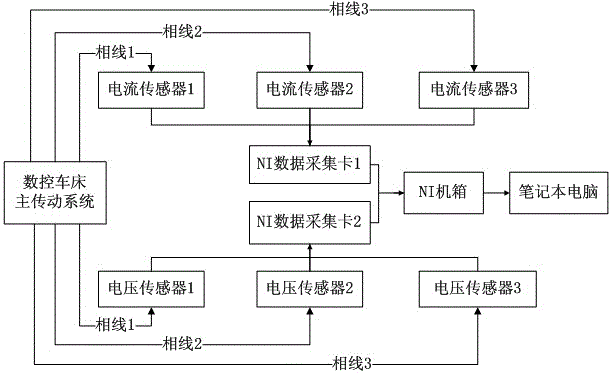
[0093] 1. Connect the power acquisition experimental device to the power input terminal of the main drive system of the CNC lathe. The sampling frequency of the voltage and current is f=1000Hz, and the average value of the power data is filtered at an interval of N=100, then f 1 =f / N=10Hz, Δt=1 / f 1 =0.1s, that is, output and store 10 power data per second. The speed range of CNC lathe CK6153i is 200~2000rpm, within this range, take n i =250rpm, 500rpm, 750rpm, 1000rpm, 1250rpm, 1500rpm, 1750rpm, make the spindle start to n i , at speed n i Idle at a constant speed for a period of time, and finally stop, collect the power data input to the spindle system in real time, and get 7 sets of data in total.

[0094] 2. Corresponding to ...


PUM


Abstract

The invention discloses a non-cutting energy obtaining method for a main transmission system of a numerically controlled lathe. A power and energy consumption value in main shaft idle operation and main shaft acceleration can be calculated according to an established main shaft idle operation and main shaft acceleration power and an energy consumption model, and coefficient values (which are obtained through experiments) of a main transmission system frequency converter, a main shaft motor no-load power Poe, a main shaft idle operation friction torque Tf, a main transmission system rotational inertia Jtot, a main shaft angle acceleration alpha and other models. The invention provides a method for obtaining relevant coefficients through the experiments; and the method comprises the steps of: obtaining the coefficients Poe and Tf through regression analysis on main shaft idle operation power data, and obtaining the coefficients Jtot and alpha through the analysis on the data such as main shaft starting power and time. The method can be used for machine tool use environment influence evaluation, mechanical machining process energy consumption calculation, machine tool and process selection based on the minimum energy consumption; and the successful execution on energy conservation and consumption reduction during mechanical manufacturing is promoted smoothly.

Description

technical field [0001] The invention relates to a method for acquiring energy consumption of a machine tool, in particular to a method for acquiring non-cutting energy consumption of a main drive system of a numerically controlled lathe. Background technique [0002] Under the current background of energy saving, emission reduction and low-carbon production, a large number of universities, enterprises and international organizations have carried out research on machine tool energy consumption. CNC lathes are widely used in the machinery manufacturing industry. The energy consumption of the main transmission system is the main component of the energy consumption of the machine tool, and the non-cutting energy consumption occupies a large proportion of the total energy consumption of the main transmission system. Therefore, it is urgent to accurately obtain the Non-cutting energy consumption lays the foundation for realizing energy saving and consumption reduction of machine t...

Claims


Application Information

Patent Timeline
Patent Type & Authority Applications(China)
IPC IPC(8): B23Q17/00
Inventor 唐任仲吕景祥贾顺
Owner ZHEJIANG UNIV
Why Eureka
Try Eureka