
Oil well casing gas collecting device

A technology of oil well casing and collection device, which is applied in pipeline systems, wellbore/well components, gas/liquid distribution and storage, etc., can solve the problems of environmental pollution, high transportation cost, incomplete collection, etc., and achieve significant environmental benefits , The effect of improving the atmospheric environment and improving the conveying efficiency

Active Publication Date: 2012-10-24
SHANGHAI YIJING ENERGY TECH
View PDF8 Cites 13 Cited by
  • Summary
  • Abstract
  • Description
  • Claims
  • Application Information

AI Technical Summary

Problems solved by technology

[0006] Purpose of the invention: To overcome the defects of incomplete collection of oil well casing gas, high transportation cost, and serious environmental pollution, and provide an oil well casing gas collection device that basically does not require additional power and does not add additional transportation equipment

Method used


Image

  • Oil well casing gas collecting device

Examples


Embodiment

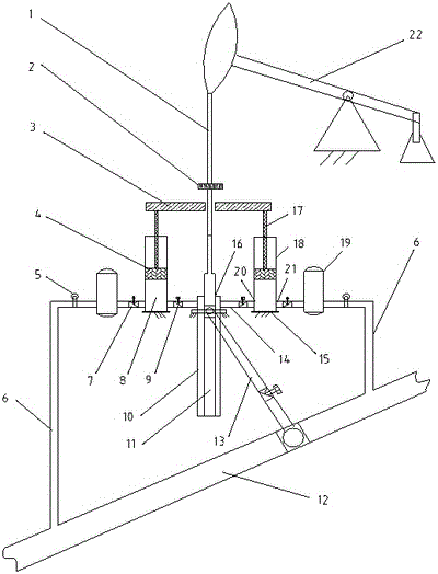
[0026] as attached figure 1 The oil well casing gas collection device shown in the figure is installed on the wellhead 16 of the oil well, and includes two casing connecting pipes 14, which are connected to the casing 10, and two one-way valves A9, two There are 18 booster pumps, two one-way valves B7, and two oil pipe connecting pipes 6 connected to the oil delivery pipe 12. Booster pump 18 contains components such as connecting rod 17, piston 4, cylinder 8, air inlet 20, air outlet 21. Two booster pumps 18 are symmetrically connected on both sides of the casing 10, and the upper ends of the two connecting rods 17 of the two booster pumps 18 are jointly connected with a pressure arm 3, and the pressure arm 3 crosses the sucker rod 1 through. The pressure arm 3 is placed horizontally, which is convenient for the sucker rod 1 and the connecting rod 17 to go up and down vertically, and the power efficiency is higher.

[0027] The casing connecting pipe 14 is connected with a p...


PUM


Abstract

The invention provides an oil well casing gas collecting device. An oil pumping pipe, an oil pumping rod and a casing are arranged in an oil well, the oil pumping rod is connected onto an oil pumping unit, and the oil pumping unit pumps crude oil from the oil pumping pipe and transports the crude oil to an oil transportation pipe. The device comprises a casing connecting pipe, a one-way valve A, a boosting pump, a one-way valve B and an oil pipe connecting pipe. The boosting pump includes a connecting rod, the upper end of the connecting is fixedly connected with a pressure arm, the upper portion of the oil pumping rod is fixedly connected with a pressure button, and the pressure button is located above the pressure arm. When the boosting pump is installed, the connecting rod is parallel to the oil pumping rod, and the pressure arm is intersected with the connecting rod but is not connected with the connecting rod. When the oil pumping rod is lifted up under the driving of the oil pumping unit, casing gas drives a piston, the connecting rod and the pressure arm to move upward under the action of self pressure. When the oil pumping rod moves downward under the action of self gravity, the pressure button presses the pressure arm to drive the connecting rod and the piston to move downward, and compressed casing gas in a compression cylinder enters the oil transportation pipe. By means of the oil well casing gas collecting device, a series of problems including difficulty in traditional oil well casing gas recovering, energy waste, environment pollution, safety hazard and the like are solved. Therefore, the oil well casing gas collecting device has obvious economic benefit and environmental-protection benefit.

Description

technical field [0001] The invention relates to a casing gas collection or delivery device fixedly connected to the oil well site in an oil field. Background technique [0002] The pumping unit is used for oil suction. When the pumping unit pumps oil, the oil flows out from the oil suction pipe, and the casing gas (or oil well associated gas, oil well natural gas) is collected in the oil well casing and flows out. [0003] Usually, after the casing gas flows out of the casing, it is directly vented or connected to a casing gas delivery pipe or a casing gas tank. Direct emptying will cause environmental pollution and waste of resources. Casing gas delivery pipe or casing gas tank collection requires special motor drive, delivery pipeline or gas storage tank, which not only increases the capital investment of the equipment, but also consumes extra power. [0004] The document with the patent application number of 201010256380.7 discloses "an oil well casing gas recovery devi...

Claims


Application Information

Patent Timeline
Patent Type & Authority Applications(China)
IPC IPC(8): E21B43/00F17D1/14
Inventor 顾建
Owner SHANGHAI YIJING ENERGY TECH
Learn More