A two-phase flow dynamic heat pipe device
A heat pipe device and flow power technology, applied in the field of heat exchange, can solve the problems of insufficient circulation power and incomplete gas-liquid separation, etc., reduce the restrictions on use conditions, solve the problems of height difference and transportation distance, and improve heat exchange efficiency Effect
- Summary
- Abstract
- Description
- Claims
- Application Information
AI Technical Summary
Problems solved by technology
Method used
Image
Examples
specific Embodiment approach 2
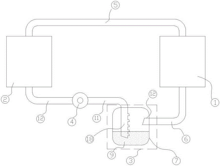
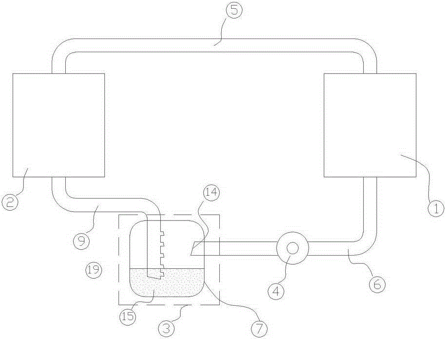
[0030] figure 2 A schematic structural diagram of the second embodiment of the system is given, in figure 1 On the basis of the above, the liquid storage and distribution device (3) is connected between the evaporator (2) and the circulation pump (4), which includes the liquid storage tank (7), the evaporator input port (15), the return hole two (19 ) and the circulation pump output end (14); the evaporator input end (15) is located at the lower part of the liquid refrigerant liquid level in the liquid storage tank (7), and the circulation pump output end (14) is located at the liquid storage tank ( 7) The upper part of the internal liquid refrigerant liquid level; the evaporator (2), condenser (1), circulation pump (4) and liquid storage and distribution device (3) are connected into a single unit through interconnecting pipes in the above order Two-phase flow dynamic heat pipe device to the circulation. The circuit control element controls the opening and running state of...
specific Embodiment approach 3
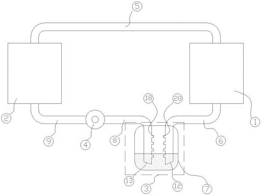
[0032] In a specific environment, in order to exchange the functions of the condenser (1) and the evaporator (2) in the system, that is, the condenser (1) acts as an evaporator, and the evaporator (2) acts as a condenser, Improvements are made on the basis of the first embodiment.
[0033] The circulation pump (4) is changed from a one-way circulation pump to a two-way power motor system (such as Roots motor) that can directly change the direction, and the part where the condenser liquid conduit (6) is located in the liquid storage and diversion device (3) and the circulation pump The design of the part of the suction pipe (8) inside the liquid storage and distribution device (3) is the same, and the simple structure diagram of this embodiment is shown in image 3 shown.
[0034] In this system, when the condenser (1) and the evaporator (2) function normally, the specific work implementation mode is the same as the specific implementation mode 1. When the condenser (1) plays ...
PUM
 Abstract
Description
Claims
Application Information
 - R&D
- Intellectual Property
- Life Sciences
- Materials
- Tech Scout
- Unparalleled Data Quality
- Higher Quality Content
- 60% Fewer Hallucinations
Browse by: Latest US Patents, China's latest patents, Technical Efficacy Thesaurus, Application Domain, Technology Topic, Popular Technical Reports.
© 2025 PatSnap. All rights reserved.Legal|Privacy policy|Modern Slavery Act Transparency Statement|Sitemap|About US| Contact US: help@patsnap.com


