
Parameter calibration method and device

A parameter calibration and parameter technology, which is applied in the field of computer vision and image measurement, can solve the problems of inconvenient implementation and failure, and achieve the effect of simple operation, simple method and high precision

Inactive Publication Date: 2012-10-24
HUAWEI TECH CO LTD
View PDF4 Cites 60 Cited by
  • Summary
  • Abstract
  • Description
  • Claims
  • Application Information

AI Technical Summary

Problems solved by technology

The two-step method divides the calibration work into two steps. First, the perspective projection matrix is ​​determined, and then the internal and external parameters of the camera are recovered from the perspective projection matrix. Since this method needs to make high-precision three-dimensional calibration blocks, it is inconvenient to implement
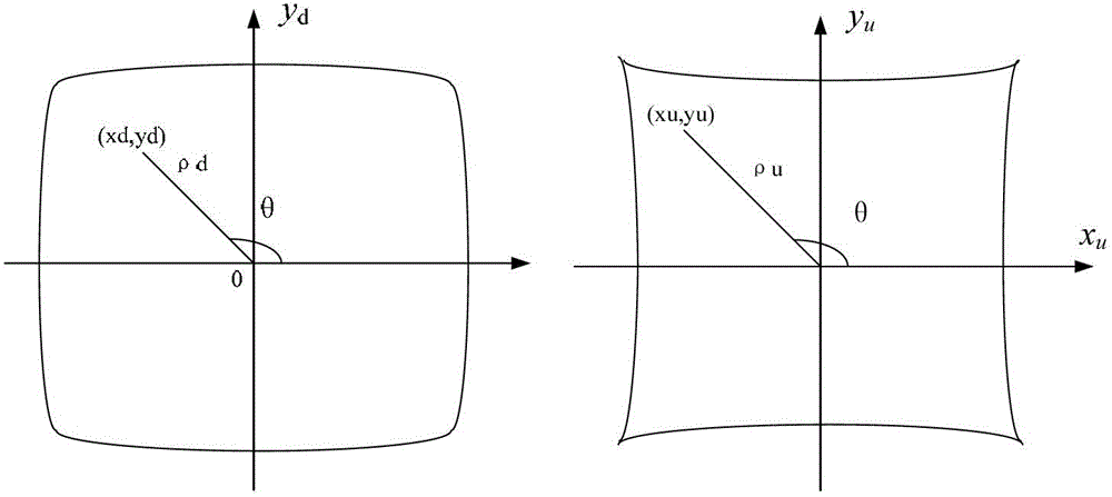
[0005] On the other hand, camera distortion modeling and calibration is also a very important content. There are more or less lens distortions in actual cameras. There are many types of camera distortion, the most important of which is radial distortion. For distortion Calibration, the classic method (such as the plane template method) first assumes that the camera is a small hole imaging model, calibrates the internal parameters of the camera, and then obtains the parameters of the polynomial distortion model through nonlinear optimization. This method is used when the distortion of the camera is not serious. works, but fails when applied to high-distortion lenses such as fisheye lenses

Method used


Image

  • Parameter calibration method and device
  • Parameter calibration method and device
  • Parameter calibration method and device

Examples


Embodiment 1

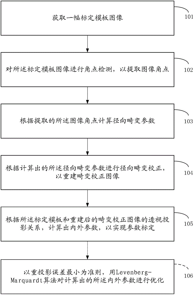
[0032] Such as figure 1 As shown, Embodiment 1 of the present invention provides a parameter calibration method, and the method includes the following steps:

[0033] 101. Acquire a calibration template image, and the calibration template image is obtained by photographing the calibration template;

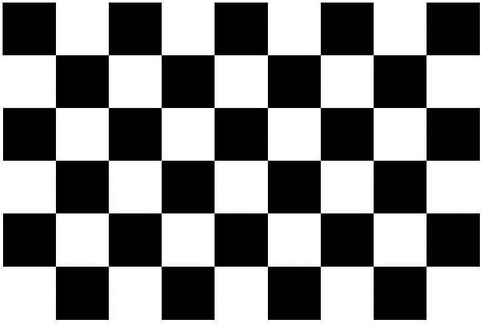
[0034] In step 101, the calibration template used in this embodiment can be a calibration template with a fixed-pitch pattern array, specifically including a checkerboard calibration template, an equidistant solid circle array calibration template, etc. Preferably, in this embodiment, the calibration template can be used The checkerboard calibration template commonly used in the camera (or camera) calibration method, specifically as figure 2 shown.

[0035] It should be noted that in order to perform radial distortion correction and parameter calibration on the camera (or camera), it is necessary to shoot a calibration template to obtain a calibration template image. The numbe...

Embodiment 2

[0122] Based on the calibration method described in Embodiment 1, such as Figure 4 As shown, Embodiment 2 of the present invention provides a parameter calibration device, which includes:

[0123] An acquisition unit 201, configured to acquire a calibration template image, the calibration template image is obtained by photographing the calibration template;


PUM


Abstract

The invention discloses a parameter calibration method. The method comprises steps of acquiring a calibration template image which is obtained by photographing of a calibration template image; performing corner detection for the calibration template image so as to extract an image corner; calculating radial distortion parameters in accordance with the extracted image corner; performing radial distortion correction in accordance with the calculated radial distortion parameters so as to reconstruct a distortion correction image; and according to a perspective projection relation of the calibration template and the reconstructed distortion correction image, calculating internal parameters and external parameters so as to achieve parameter calibration, wherein internal parameters and external parameters comprise internal parameter matrixes, rotating vectors and translation vectors. The invention also provides a parameter calibration device. The method and the device can be applied to parameter calibration of imaging devices such as video cameras or cameras under the condition of high distortion, the operation is simple and the precision is high.

Description

technical field [0001] The invention relates to the fields of computer vision and image measurement, in particular to a camera calibration method and device. Background technique [0002] In the process of image measurement and computer vision applications, in order to determine the relationship between the three-dimensional geometric position of a point on the surface of a space object and its corresponding point in the image, it is necessary to establish a geometric model of imaging. The parameters of the device, under most conditions, these parameters must be obtained through experiments and calculations. The process of solving the parameters is called camera calibration (or camera calibration). Taking camera calibration as an example, existing camera calibration methods can generally be divided into two categories: traditional calibration methods based on calibration objects, and self-calibration methods based on image sequences. [0003] Among the traditional calibrati...

Claims


Application Information

Patent Timeline
IPC IPC(8): G06T7/00
CPCG06T7/00G06T2207/30208G06T7/80G06T5/80G06T2207/10004G06T2207/10016
Inventor 朱云芳李水平杜歆
Owner HUAWEI TECH CO LTD
Learn More