Large-power multilevel converter based on high-frequency isolation transformer

A multi-level converter and isolation converter technology, applied in the field of current conversion, can solve the problems of difficult DC side capacitor voltage balance, complex structure, complex control, etc., to achieve modular design, voltage stress reduction small effect

Inactive Publication Date: 2012-10-24
CHINA UNIV OF MINING & TECH (BEIJING)
View PDF1 Cites 26 Cited by
  • Summary
  • Abstract
  • Description
  • Claims
  • Application Information

AI Technical Summary

Problems solved by technology

However, this method is complex to control, and the introduction of multiple independent DC power sources will also cause complicated structures in practice, which is quite difficult
[0005] Both diode-clamped inverters and flying-capacitor inverters have unbalanced capacitors on the DC side
However, when the circuit structure is higher than three-level, the balance of the DC side capacitor voltage is difficult to achieve
Therefore, the diode embedded multi-level structure has not been able to be used in high-power converter systems at higher supply voltage levels

Method used


Image

  • Large-power multilevel converter based on high-frequency isolation transformer
  • Large-power multilevel converter based on high-frequency isolation transformer
  • Large-power multilevel converter based on high-frequency isolation transformer

Examples


Embodiment 1

[0035] The single-phase topology of the high-power multilevel converter based on high-frequency isolation conversion consists of an input stage, an intermediate stage and an output stage to form a single-phase five-level topology.

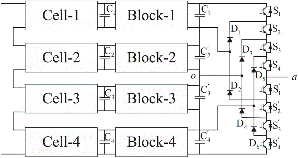
[0036] Among them, refer to figure 1 with figure 2, the input stage is a single-phase cascaded H-bridge rectifier, and the single-phase cascaded H-bridge rectifier includes 4 H-bridge rectifier circuits Cell-n connected in series, where n=1,2,3,4, each H-bridge The rectification circuit Cell includes 4 IGBT modules with anti-parallel diodes, the midpoint of the first bridge arm of the first H-bridge rectification circuit Cell-1 and the second bridge arm midpoint of the fourth H-bridge rectification circuit Cell-4 The single-phase AC input voltage is connected between them, the midpoint of the second bridge arm of the remaining H-bridge rectifier circuit Cell is connected to the midpoint of the first bridge arm of the next H-bridge rectifier circu...

Embodiment 2

[0040] The three-phase topology of the high-power multilevel converter based on high-frequency isolation conversion consists of an input stage, an intermediate stage and an output stage to form a three-phase five-level topology.

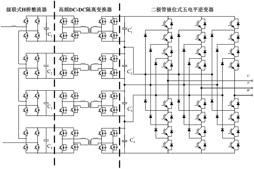
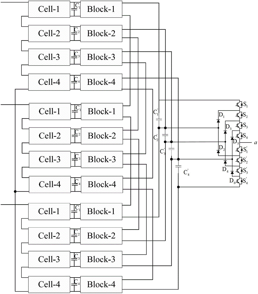
[0041] Among them, refer to image 3 with Figure 4 , the input stage is a three-phase cascaded H-bridge rectifier, the three-phase cascaded H-bridge rectifier includes 3 single-phase cascaded H-bridge rectifiers, and each phase has 4 H-bridge rectifier circuits Cell-n, where n=1, 2, 3, 4, a total of 12 H-bridge rectifier circuits. In each phase, the midpoint of the first bridge arm of the first H-bridge rectifier circuit Cell-1 is used as the three-phase voltage input terminal, and the midpoint of the second bridge arm of the fourth H-bridge rectifier circuit Cell-4 is connected to each other .

[0042] The intermediate stage is a three-phase high-frequency DC-DC isolation converter. The three-phase high-frequency DC-DC isolation converter includ...

Embodiment 3

[0045] The application of the high-power multi-level converter based on high-frequency isolation conversion of the present invention in the converter technology will be described below with Embodiment 3.

[0046] refer to Figure 5 , in the prior art multilevel converter topology using power frequency transformers, the middle points of the first bridge arms of the three H-bridge rectifier circuits are connected to a common point, and the outputs of the three-phase inverters are connected to the three phase motor. On a single bridge arm of each H-bridge rectifier circuit, the conduction state of each switch tube can be divided into -1, 0, 1. The second and third switch tubes T2 and T3 of the H-bridge rectifier circuit are in the 0 state, the first and second switch tubes T1 and T2 of the H-bridge rectifier circuit are in the 1 state, and the third and fourth switches of the H-bridge rectifier circuit are in the 0 state. The conduction of tubes T3 and T4 is in the -1 state. F...


PUM


Abstract

The invention relates to a large-power multilevel converter based on a high-frequency isolation transformer, and the large-power multilevel converter comprises a main circuit and a phase-shift control circuit of the main circuit, wherein an input stage of the main circuit is a cascade-type H-bridge rectifier, an intermediate stage of the main circuit is a high frequency direct current-direct current (DC-DC) isolation converter, and an output stage of the main circuit is a diode embedded multilevel inverter. Each H bridge rectification circuit of the cascade-type H-bridge rectifier outputs identical direct-current voltage, and the phase-shift control circuit controls the capacitance voltage at the DC side by controlling a phase shifting angle of each H-bridge rectification circuit. The large-power multilevel converter has advantages that since the cascade-type H-bridge rectifier is adopted, each H-bridge rectification circuit outputs identical DC voltage, and the phase-shift control circuit controls the capacitance voltage at the DC side by controlling the phase-shifting angle of each H-bridge rectification circuit, the unbalance problem of the capacitance voltage at the DC side in a topological structure can be flexibly solved, the independent control for the DC-side capacitance voltage is realized, the voltage stress on each switch device is reduced, and the modularization design is favored.

Description

technical field [0001] The invention relates to the converter technology, in particular to a high-power multi-level converter based on high-frequency isolation conversion. Background technique [0002] With the development of modern power electronics technology, multi-level converter technology enables low-voltage power switch tubes to complete high-voltage and high-power energy conversion and transmission. The multi-level circuit structure has small output voltage harmonics, low switching frequency, It can improve the EMI characteristics of the device and many other advantages, and has been widely used in frequency conversion speed regulation of medium and high voltage high-power motors, DC transmission and other occasions. Compared with traditional two-level converters, multi-level converters have great advantages: (1) As the number of levels increases, output voltage harmonics decrease; (2) The voltage stress on each switching device (3) With the increase of the number o...

Claims


Application Information

Patent Timeline
Patent Type & Authority Applications(China)
IPC IPC(8): H02M7/25H02M3/335H02M7/537
Inventor 程红王聪李瑶璞张国澎卢其威邹甲王俊
Owner CHINA UNIV OF MINING & TECH (BEIJING)
Why Eureka
Try Eureka