High-dynamic range image sensing circuit and high-dynamic range image reading method

A high dynamic range, image sensing technology, used in TVs, electrical components, color TVs, etc.

Active Publication Date: 2012-10-24
PIXART IMAGING INC
View PDF5 Cites 23 Cited by
  • Summary
  • Abstract
  • Description
  • Claims
  • Application Information

AI Technical Summary

Problems solved by technology

[0004] The disadvantage of this prior art is that there are two options with fixed conv

Method used


Image

  • High-dynamic range image sensing circuit and high-dynamic range image reading method
  • High-dynamic range image sensing circuit and high-dynamic range image reading method
  • High-dynamic range image sensing circuit and high-dynamic range image reading method

Examples


Embodiment Construction

[0054] The drawings in the present invention are all schematic, mainly intended to show the functional relationship between each device and each component, and the shapes, thicknesses and widths are not drawn to scale.

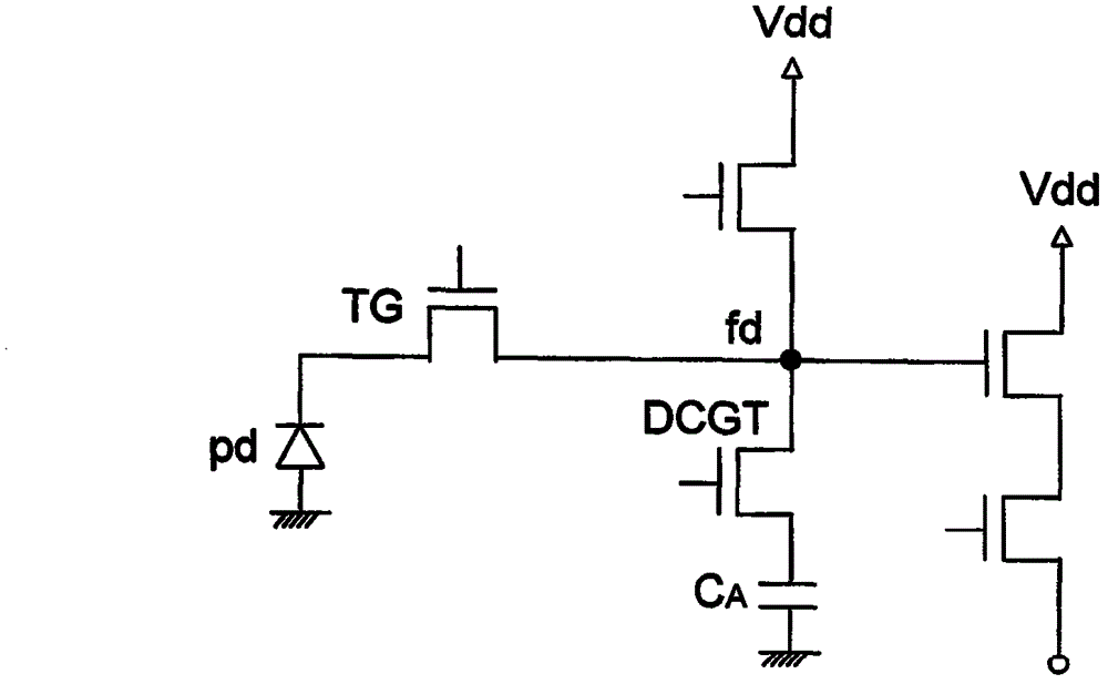
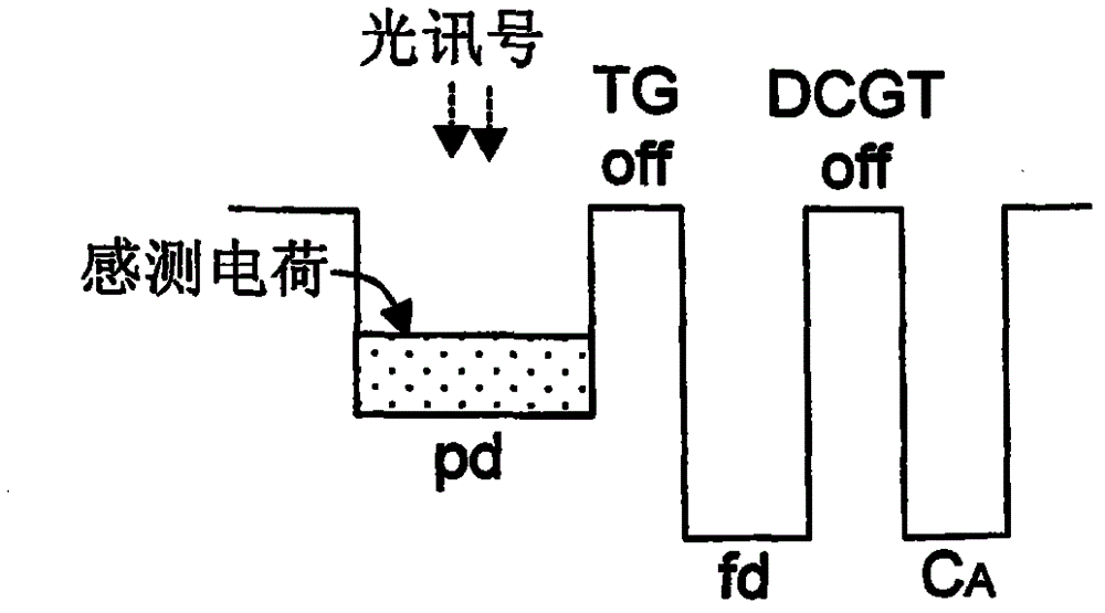
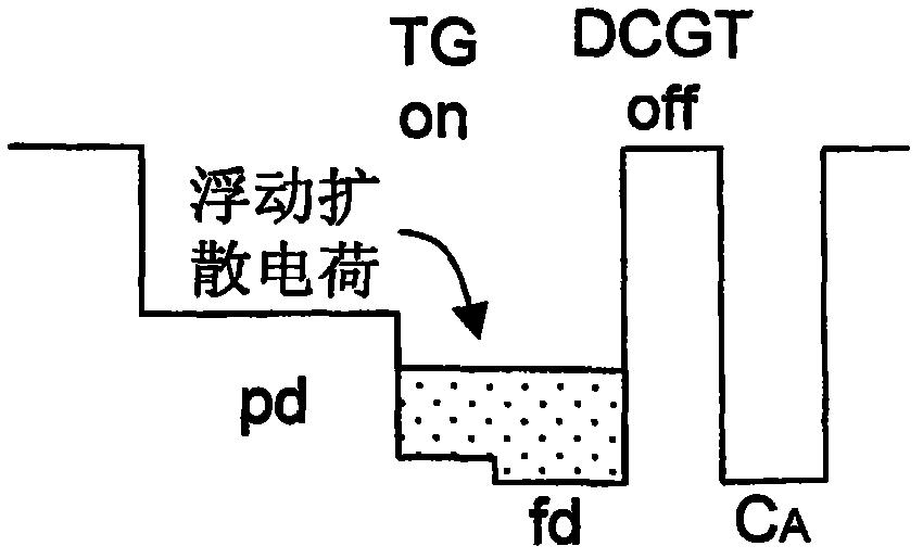
[0055] Figures 3A-3L A first embodiment of the invention is shown. The high dynamic range image sensing circuit includes an image sensing element 10 formed on a first conductive type substrate, such as but not limited to a P-type semiconductor substrate, and a signal readout circuit 20 . see Figure 3A , showing the circuit diagram of this embodiment, wherein the image sensing element includes: a light sensing unit pd, such as but not limited to a photodiode, a photogate, or a photoconductor, used to receive light signals to generate and store sensing charges; The floating diffusion node fd is used to store the floating diffusion charge; the transfer switch, in this embodiment, is a transfer transistor TG, coupled between the photo-sensing unit pd and the f...


PUM


Abstract

The invention provides a high-dynamic range image sensing circuit with adaptive conversion gain and a high-dynamic range image reading method. The high-dynamic range image sensing circuit comprises a variable capacitor. The capacitance value of the variable capacitor is adjusted according to sensed lightness or internal feedback control so as to adaptively adjust the conversion gain when a signal representing a pixel image sensed by an image sensing element is read. When signals are read per period, the signals within different dynamic ranges can be respectively read for more than two times so as to enhance the accuracy of the signals.

Description

technical field [0001] The present invention relates to a high dynamic range image sensing circuit and a high dynamic range image reading method, in particular to a high dynamic range image sensing circuit and high Dynamic range image reading method. Background technique [0002] figure 1 A circuit diagram of a high dynamic range image sensing device disclosed in US Pat. No. 7,075,049 is shown. Such as figure 1 As shown, compared with the traditional four-transistor (4T) image sensing element, the high dynamic range image sensing element adds a dual conversion gain transistor (DCGT) and a capacitor CA to switch the conversion of the read signal. gain. Figure 2A and 2B ,as well as Figure 2C and 2D , respectively displayed in figure 1 In the diagram, the level diagram of each node of the high dynamic range image sensing device under low brightness and high brightness, and describes the transfer of charge sensed by the high dynamic range image sensing device during op...

Claims


Application Information

Patent Timeline
IPC IPC(8): H04N5/355H01L27/146
Inventor 颜文正陈经纬李兆琪
Owner PIXART IMAGING INC
Why Eureka
Try Eureka