Heat exchanger for a hot fuel cell

一种热交换器、燃料电池的技术,应用在燃料电池热交换、燃料电池、燃料电池应用等方向,能够解决增加热电联产系统成本等问题

Active Publication Date: 2012-10-24
SN DETUDE & DE CONSTR DE MOTEURS DAVIATION S N E C M A
View PDF3 Cites 6 Cited by
  • Summary
  • Abstract
  • Description
  • Claims
  • Application Information

AI Technical Summary

Problems solved by technology

However, the use of this material would significantly increase the cost of the CHP system, which is undesirable especially for household appliances

Method used


Image

  • Heat exchanger for a hot fuel cell
  • Heat exchanger for a hot fuel cell
  • Heat exchanger for a hot fuel cell

Examples


Embodiment Construction

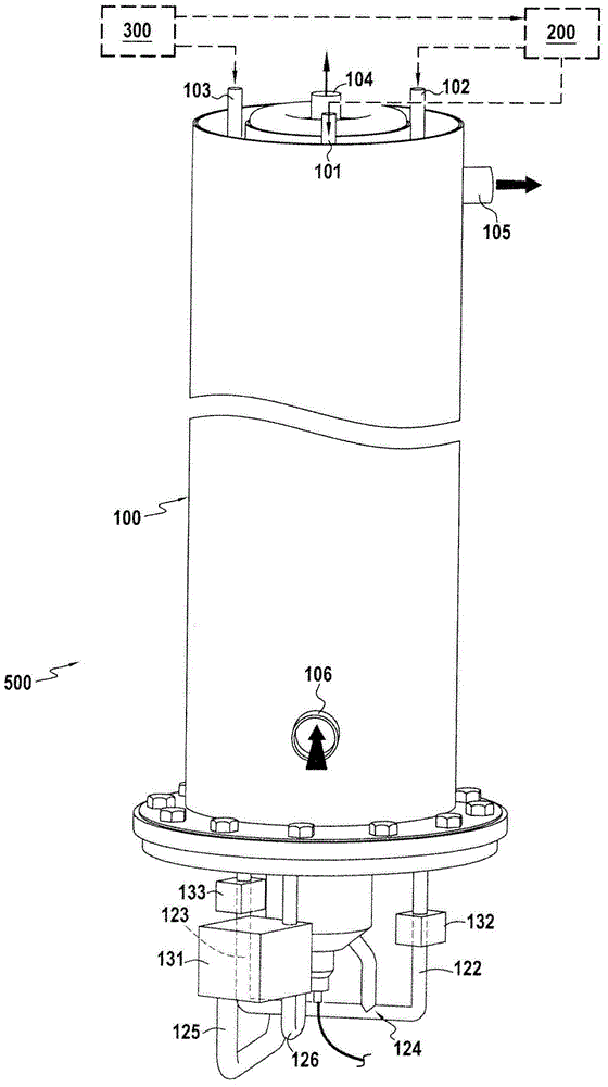
[0040] figure 1 A combined heat and power system 500 according to the invention is shown.

[0041] The combined heat and power system 500 includes:

[0042] The heat exchanger 100 in the first embodiment of the present invention; and

[0043] Thermal fuel cell 200 and reformer 300 downstream of heat exchanger 100 .

[0044] In a known manner, thermal fuel cells operate at very high temperatures, above 650°C. As an example, such a cell is a solid oxide fuel cell, commonly referred to as an SOFC, which operates at a temperature of about 900°C. The structure and operation of fuel cells of that type are known and will not be described in more detail here.

[0045] In order to operate (i.e., to enable the electrochemical redox reaction to proceed simultaneously with electricity generation), the electrodes of the cell need to be supplied separately with a fuel gas (typically hydrogen) and an oxidant gas (i.e., oxygen contained in the air stream supplied to the cell, for example ...


PUM


Abstract

The invention relates to a heat exchanger (100) that is intended to operate at the outlet of a hot fuel cell that supplies the exchanger with oxidizing and fuel gases, said heat exchanger comprising: a first oxidizing gas flow circuit (111); a second fuel gas flow circuit (112); a pre-mixing chamber (142) supplied with fuel gases from at least the second circuit and moreover supplied with oxidizing gases; a combustion chamber (140) supplied with the gas mixture from the pre-mixing chamber and moreover supplied with oxidizing gases from the first circuit; and a flue gas flow circuit (114) that receives the flue gases coming from the combustion chamber. The first oxidizing gas flow circuit, the second fuel gas flow circuit, the combustion chamber, and the flue gas flow circuit are submerged in a single heat transfer fluid.

Description

technical field [0001] The invention relates to the field of heat exchanger capable of recovering heat contained in high-temperature gas. In particular the invention relates to a heat exchanger for use at the outlet of a hot fuel cell. Background technique [0002] Fuel cells generate electricity while performing electrochemical redox reactions. To do this, the electrodes of the battery need to be supplied separately with fuel (usually hydrogen) and oxidant (that is, oxygen, which is extracted from the vapor of the air introduced into the core of the battery). [0003] Thermal fuel cells, such as those of the Solid Oxide Fuel Cell (SOFC) type, operate at very high temperatures (about 900° C.). This makes them particularly advantageous for use in so-called "cogeneration" systems, ie systems that simultaneously generate heat and electricity. Such combined heat and power systems can be used equally well in industrial applications and in domestic appliances (eg to generate he...

Claims


Application Information

Patent Timeline
Patent Type & Authority Applications(China)
IPC IPC(8): F24H1/28F23D14/02F23L7/00H01M8/06F24D18/00
CPCY02B90/14Y02B90/16H01M8/0662H01M2250/405H01M8/04014Y02E60/50Y02E60/525F24H1/287H01M8/04074F24H2240/10H01M2250/10H01M2008/1293H01M8/0618Y02P80/15Y02B90/10F24D2101/30F24D2103/13F24D18/00
Inventor 卡梅·勒文布吕克多米尼克·因德西阿卜杜勒-卡里姆·布哈勒法班诺瓦·塔尔博特
Owner SN DETUDE & DE CONSTR DE MOTEURS DAVIATION S N E C M A
Why Eureka
Try Eureka