Pressure plate clamping mechanism

A technology of clamping mechanism and pressure plate, applied in clamping, metal processing mechanical parts, supports, etc., can solve problems such as workpiece cannot be processed.

Active Publication Date: 2012-10-31
华域视觉科技(长沙)有限公司
View PDF6 Cites 4 Cited by
  • Summary
  • Abstract
  • Description
  • Claims
  • Application Information

AI Technical Summary

Problems solved by technology

There may even be extreme cases where workpiec...

Method used


Image

  • Pressure plate clamping mechanism
  • Pressure plate clamping mechanism
  • Pressure plate clamping mechanism

Examples


Embodiment Construction

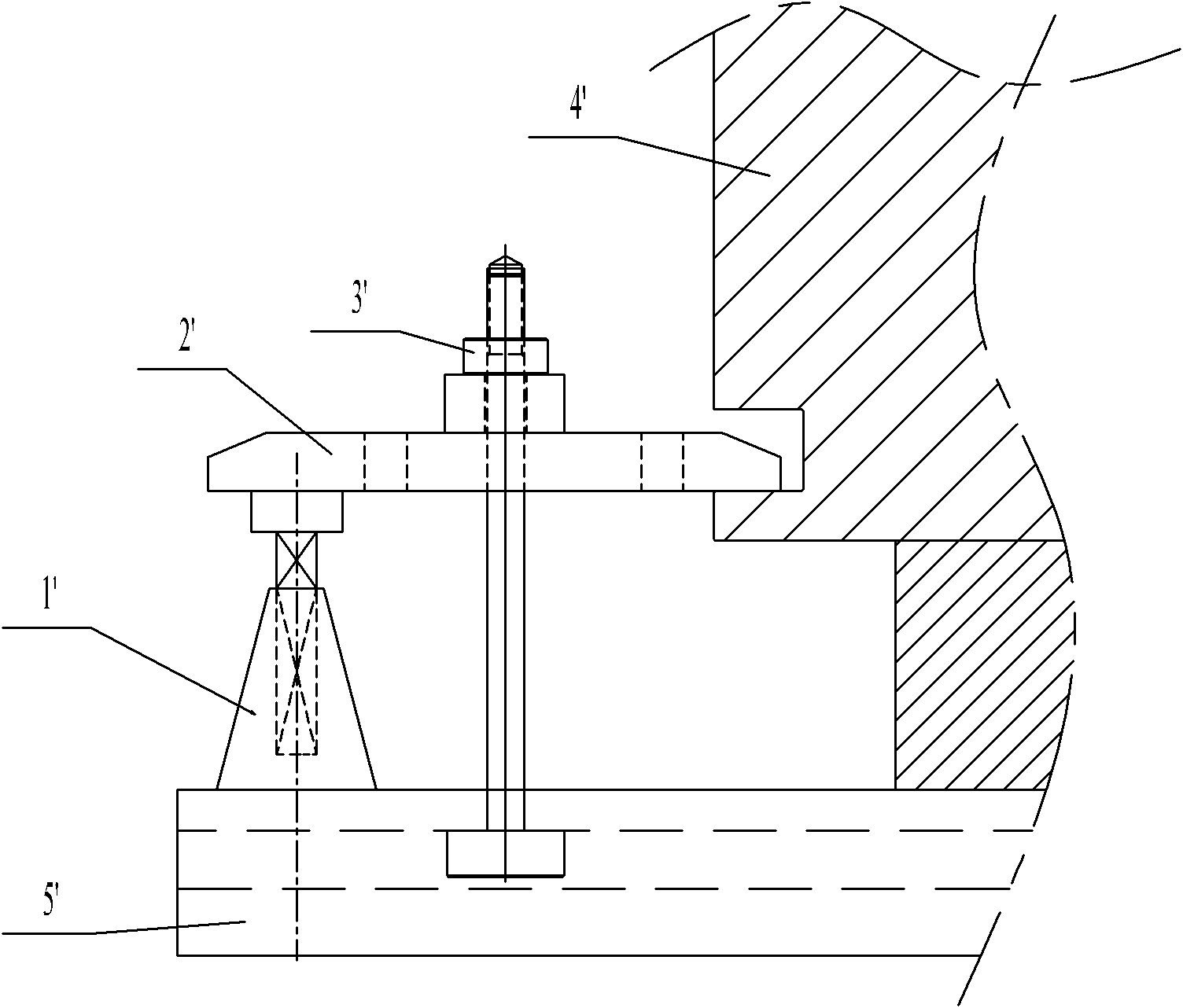
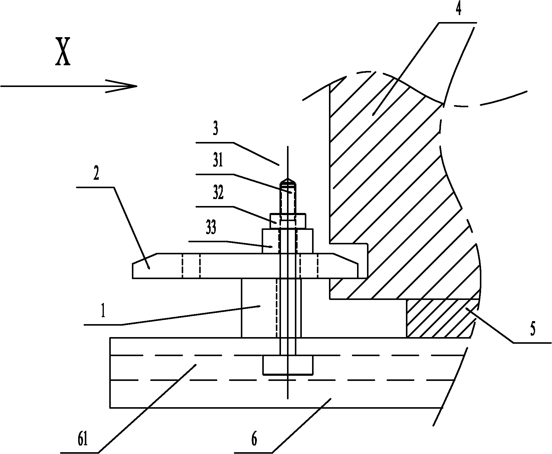
[0020] see image 3 , is the pressing plate clamping mechanism involved in the present invention. The invention is suitable for workpiece clamping (such as large plastic moulds) on horizontal machine tools. The pressing plate clamping mechanism includes a pressing plate 2 and a force applying rod 3 passing through the pressing plate 2. One end of the pressing plate 2 is supported on the pad 1, and the other end is used for pressing the workpiece. The cushion block 1 includes a support portion and a relief portion, the top surface 11 of the support portion is in contact with the pressure plate 2, and the relief portion is provided with a relief hole 15 for the force applying rod 3 to pass through, and the relief portion There is a gap between the top surface 12 of the upper part and the pressing plate 2.

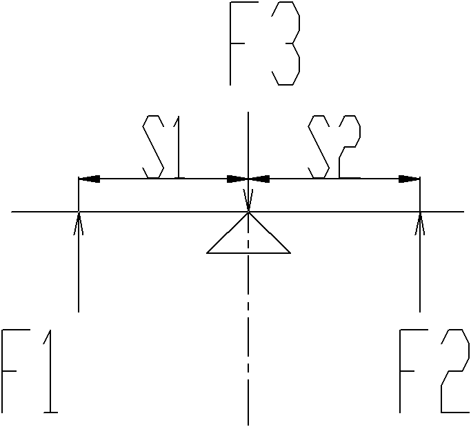
[0021] The bottom of the pressing plate 2 forms first and second contact surfaces 21 and 22 on both sides of the force applying rod 3 respectively. The top of the spacer 1...


PUM


Abstract

The invention discloses a pressure plate clamping mechanism. The pressure plate clamping mechanism comprises a pressure plate and a force application rod penetrating the pressure plate, one end of the pressure plate is supported on a cushion block, the other end of the pressure plate is used for compressing a workpiece, the cushion block comprises a support part and an abdication part, the top surface of the support part is in contact with the pressure plate, the abdication part is provided with an abdication hole for enabling the force application rod to penetrate, and a gap is arranged between the top surface of the abdication part and the pressure plate. The pressure plate clamping mechanism disclosed by the invention can achieve the purpose of expanding the range of applications of ordinary clamping by reducing the spatial size of the cushion block. The force at the fulcrum of the cushion block can be balanced at the lower part of the whole cushion block by ingenious force conversion. Simultaneously, the pressure plate clamping mechanism can ensue that the force at the fulcrum can be close to the workpiece as far as possible and ensure the reasonable equilibrium of a lever. Compared with the ordinary clamping, the stress situation of theoretical calculation is the same. The pressure plate clamping mechanism disclosed by the invention has the characteristics of simple and compact structure, and stability and reliability in operation.

Description

technical field [0001] The invention belongs to a tooling fixture for CNC auxiliary matching of a machining center, and in particular relates to a clamping mechanism for a clamping plate used for workpiece clamping of a horizontal machine tool. Background technique [0002] CNC technology is widely used in industrial manufacturing. The workpiece to be manufactured is first placed on the workbench; then fixed on the T-slot worktable through the necessary clamping means; through repeated calibration of the workpiece reference, the cutting process is finally carried out. The current common practice is to use the principle of leverage, such as figure 2 , the two forces F1 and F2 use the fulcrum to maintain the balance of the forces. The specific method is: a threaded headrest assembly 1' that can adjust the height is connected to the side groove or plane of the workpiece 4' through a large pressure plate 2', and the headrest assembly 1' and the workpiece 4' are connected. Bet...

Claims


Application Information

Patent Timeline
IPC IPC(8): B23Q3/06
Inventor 王辉
Owner 华域视觉科技(长沙)有限公司
Why Eureka
Try Eureka