Driving leg mechanism for footed robot

A technology for driving legs and robots, which is applied in the fields of motor vehicles, transportation and packaging, etc. It can solve the problems of increasing thigh weight and structural space, complicated knee joint mechanism, and small working space at the end of the foot, and achieves light weight, compact structure, and high mobility. large space effect

Inactive Publication Date: 2012-10-31
ANHUI UNIVERSITY OF TECHNOLOGY
View PDF5 Cites 6 Cited by
  • Summary
  • Abstract
  • Description
  • Claims
  • Application Information

AI Technical Summary

Problems solved by technology

However, the driving motor and its transmission device increase the weight and structural space of the thigh, the knee joint mechanism is complex, there are many motion pairs, and the working space at the foot end is small

Method used


Image

  • Driving leg mechanism for footed robot
  • Driving leg mechanism for footed robot

Examples


Embodiment Construction

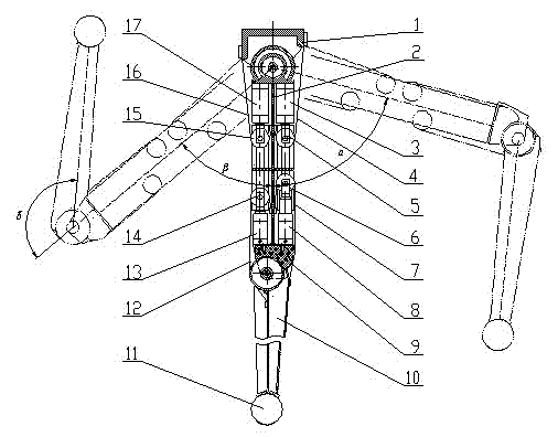
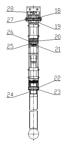
[0023] The present invention will be further described below in conjunction with accompanying drawing:

[0024] Hip joint column 28 is fixedly connected with femur 2, and its endoporus cooperates with the outer ring of bearing 19, and the inner ring of bearing 19 cooperates with hollow shaft 18, and the two ends of hollow shaft 18 are fixedly connected with leg support 1 with bolt 27, Forms the hip joint of the thigh. The upper end of the calf bone 10 is affixed to the knee joint column 24, and the joint pad 9 is fixed on the lower end of the femur 2 by screws, and is in contact with the cylindrical surface of the knee joint column 24 to bear the main load of the knee joint; meanwhile, the femur 2. The lug at the lower end is fixedly connected to the rivet 22, and the elastic sleeve 23 is fixedly installed in the through hole of the knee joint column 24. The rivet 22 and the elastic sleeve 23 cooperate with each other to form an auxiliary hinge between the femur 2 and the knee...


PUM


Abstract

The invention provides a driving leg mechanism for a footed robot, belonging to the technical field of footed robots. The driving leg mechanism comprises a leg support, a thighbone, a thigh forward swing cylinder, a thigh front stay cable, a thigh front pulley, a crus front pulley, a crus front stay cable, a crus forward swing cylinder, a joint mat, a focile, a ball-shaped foot, a crus rear stay cable, a crus backswing cylinder, a crus rear pulley, a thigh rear pulley, a thigh rear stay cable, a thigh backswing cylinder, a knee-joint pillar and a hip joint pillar, wherein the leg support is hinged with the hip joint pillar to form a hip joint, the upper end of the thighbone is fixedly connected with the hip joint pillar, the joint mat is arranged at the lower end of the thighbone and is hinged with the knee-joint pillar, a knee joint is composed of the thighbone, the joint mat and the knee-joint pillar, the upper end of the focile is fixedly connected with the knee-joint pillar, and the lower end of the focile is fixedly connected with the ball-shaped foot. The driving leg mechanism has the advantages of compact structure, light weight, low energy consumption, capability of realizing rapid joint movements, stable carrying capacity, large foot end movement space, good buffering performance and long service life.

Description

technical field [0001] The invention belongs to the technical field of legged robots, and in particular relates to a driving leg mechanism of a legged robot. Background technique [0002] The footed robot needs to control the movement of the calf relative to the thigh and the thigh relative to the body through the leg mechanism composed of the knee joint and the hip joint, so as to realize various gait movements of the footed robot. In order to improve the motion performance of the legged robot, the leg mechanism composed of the hip joint and the knee joint needs to have a large working space at the foot end; It is light, takes up little space, and is easy to realize fast motion control of leg joints. In the leg mechanisms of existing legged robots, motors and their transmissions or hydraulic cylinders and linkages are usually used to drive the joints to rotate. Although the motor drive technology is mature and the two-way motion control is stable and reliable, the motor a...

Claims


Application Information

Patent Timeline
Patent Type & Authority Applications(China)
IPC IPC(8): B62D57/032
Inventor 张玉华詹玉新
Owner ANHUI UNIVERSITY OF TECHNOLOGY
Why Eureka
Try Eureka