Opened type airplane hot-gas anti-icing test device

A test device and open technology, applied in the field of open aircraft hot air anti-icing chamber test device, can solve the problems of high processing cost, lack of experimental research work, and great influence of heat transfer, etc., and achieve the effect of reducing test cost

Inactive Publication Date: 2012-10-31
BEIHANG UNIV
View PDF5 Cites 10 Cited by
  • Summary
  • Abstract
  • Description
  • Claims
  • Application Information

AI Technical Summary

Problems solved by technology

However, there are many factors in the internal structure of the aircraft hot air anti-icing chamber, including the arrangement of the hot air jet holes of the flute tube, the diameter and spacing of the jet holes, the relative position of the jet hole and the cavity, the relative position of the flute tube in the cavity, etc. It presents serious three-dimensional characteristics, and the heat transfer caused by it is very complicated. The structure in the chamber has a great influence on the heat transfer between the hot gas and the inner wall of the chamber, thus affecting the thermal efficiency of the anti-icing chamber
At present, the research on the mechanism of the structure affecting the flow and heat transfer in the hot gas anti-icing chamber is not comprehensive, especially the lack of experimental research work, so that the domestic design and development of this structure has to rely on foreign suppliers
In order to get rid of the dependence on foreign technology as soon as possible, so that my country can independently develop the structure of the hot gas anti-icing chamber, it is very important to carry out relevant experimental work. The traditional hot gas anti-icing chamber experimental device is made in order to ensure that the chamber withstands internal pressure. The tube cavity is integrated and formed by welding, but considering that the leading edge surface of the hot gas anti-icing cavity is an airfoil structure with continuously variable curvature, the processing cost is very high, and the various structures concerned mainly focus on the replacement of the internal flute tube , the invention discloses an open-type aircraft hot air anti-icing chamber experimental device. Under the premise of ensuring that the pressure resistance characteristics of the chamber remain unchanged, the flexible assembly of the chamber and flute-shaped pipes of different structures and diameters is realized, and the costly test is solved. Installation cost issue

Method used


Image

  • Opened type airplane hot-gas anti-icing test device
  • Opened type airplane hot-gas anti-icing test device
  • Opened type airplane hot-gas anti-icing test device

Examples


Embodiment Construction

[0040] The present invention will be further described in detail below in conjunction with the accompanying drawings and embodiments.

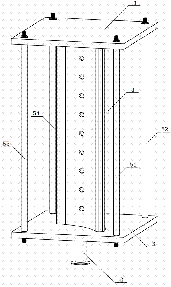
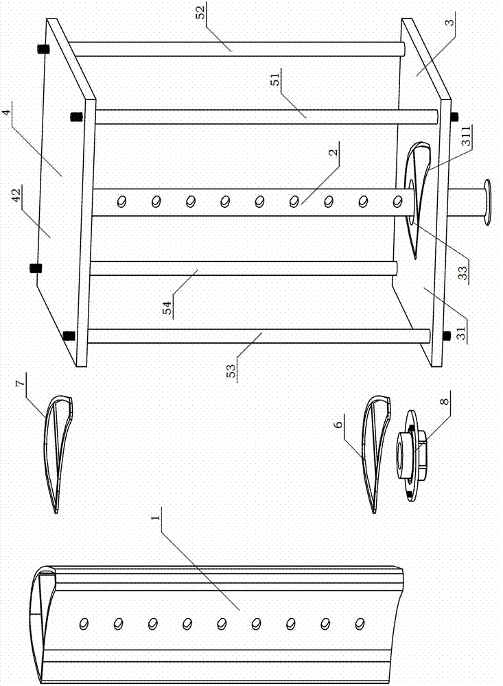
[0041] see Figure 6 , Figure 6AAs shown, the cavity 1 of the aluminum airfoil type hot air anti-icing cavity is divided into the first wing cavity 11 and the second wing cavity 12 through the partition plate 13, and there is a gap between the partition plate 13 and the anti-icing wall surface 17 at the leading edge of the cavity. There is a slit 14, which is used to transfer the hot air entering from the air supply flute 2 to the second wing chamber 12; the airfoil hot air anti-icing chamber cavity 1 is provided with a plurality of exhaust holes 15, so The exhaust hole 15 is used to discharge the hot air in the second wing cavity 12 . The air supply flute tube 2 is placed in the first wing chamber 11, and the high-pressure hot air flow entering from the air supply flute tube 2 is sprayed into the first wing chamber 11 at high speed through...


PUM


Abstract

The invention discloses an opened type airplane hot-gas anti-icing test device. A positioning end of a gas supply flute-shaped pipe is mounted in a counter positioning hole of a second de-icing cavity board; a second gasket is arranged in a second wing-shaped groove; a first gasket is arranged in a first wing-shaped groove; a conformal end cover assembly is mounted on the first de-icing cavity board; the both ends of a wing-shaped hot-gas anti-icing cavity are respectively mounted between a first de-icing cavity board and the second de-icing cavity board; four fastening and positioning rods pass through corresponding mounting holes of the first de-icing cavity board and the second de-icing cavity board, and are fastened at the both ends of the positioning rod through nuts, so that the wing-shaped hot-gas anti-icing cavity is mounted by clamping the first de-icing cavity board and the second de-icing cavity board clamp. A test device provided by the invention can be used for intensive study on the property that the complex structure of the wing-shaped hot-gas anti-icing cavity influences internal flow heat transmission, so that the influence factors of the heat property of the de-icing cavity can be comprehensively revealed. Therefore, the pre-design of the complex structure of the de-icing cavity and gas supply parameters can be carried out under the condition that the de-icing heat load distribution is known. Furthermore, whether the given de-icing cavity can meet de-icing requirements or not can be subjected to scientific and rapid general performance evaluation.

Description

technical field [0001] The invention relates to a test device suitable for the research of flow and heat transfer characteristic parameters inside a hot air anti-icing chamber in the aircraft field, more particularly, an open type aircraft hot air anti-icing chamber test device. Background technique [0002] When an aircraft flies under icy weather conditions, suspended supercooled water droplets will freeze on the surfaces of components such as wings, propellers, engine intakes, windshields, and sensors. The problem of icing will seriously affect the safety of aircraft flight. [0003] The hot gas anti-icing system is the most commonly used anti-icing system at present by introducing high-temperature gas from the engine to heat the anti-icing surface. Since the energy of the hot gas anti-icing system comes from the engine, improving the efficiency of the hot gas anti-icing system is of great significance for reducing energy compensation loss and increasing engine thrust. ...

Claims


Application Information

Patent Timeline
Patent Type & Authority Applications(China)
IPC IPC(8): B64F5/00B64F5/60
Inventor 林贵平彭珑曾宇卜雪琴郁嘉蔡琰
Owner BEIHANG UNIV
Why Eureka
Try Eureka