Bearing propelled stirring quenching device

A push-type stirring and quenching device technology, which is applied in the direction of quenching devices, heat treatment equipment, furnaces, etc., can solve the problems of slow and slow series cooling frequency, and the finished product cannot meet the design requirements, and achieve the effect of small convective loss

Active Publication Date: 2012-10-31
DALIAN GRANDWAY BEARING
View PDF5 Cites 6 Cited by
  • Summary
  • Abstract
  • Description
  • Claims
  • Application Information

AI Technical Summary

Problems solved by technology

The heat treatment of super large bearing parts plays a very important role in bearing manufacturing. Because the effective thickness of super large bearings is too large, it far exceeds the hardenability of the material. At the same time, because large bearing rings release a lot of heat during quenching and take a long time , so that the local oil temperature rises faster. The conventional quenching cooling method adopts the method of serial cooling through the crane through the crane. Becaus

Method used


Image

  • Bearing propelled stirring quenching device
  • Bearing propelled stirring quenching device
  • Bearing propelled stirring quenching device

Examples


Embodiment Construction

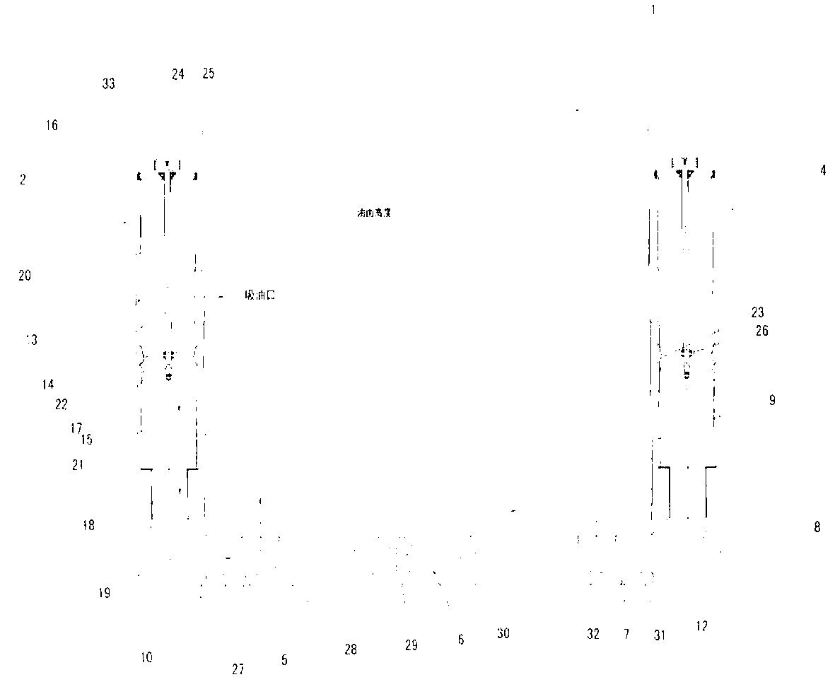
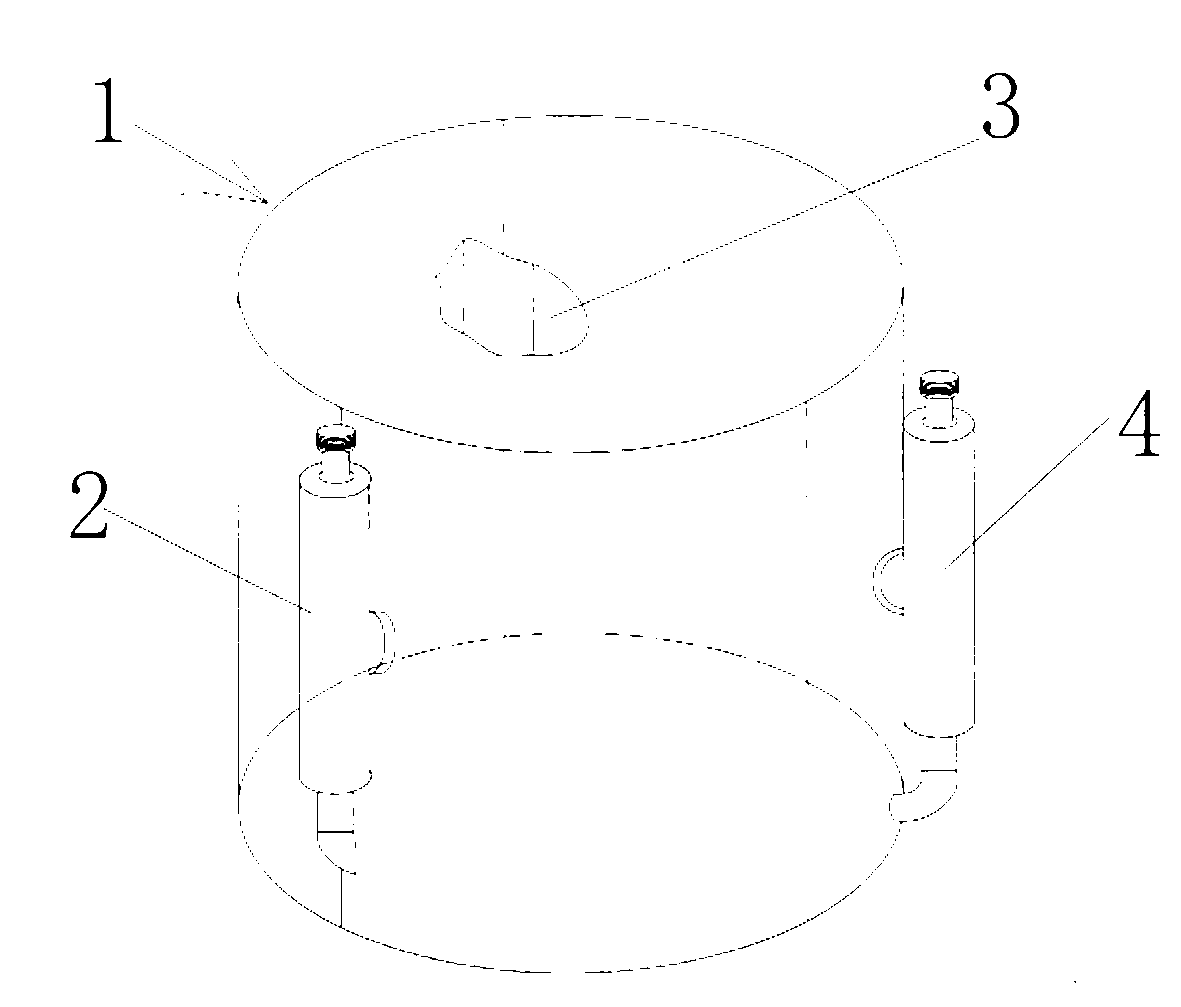
[0024] A bearing-propelled stirring quenching device, comprising a quenching oil pool 1, a first oil propeller 2, a second oil propeller 3, a third oil propeller 4, a first deflector 5, a second deflector 6, The third deflector 7 and the shield 8 of the upper opening are characterized in that:

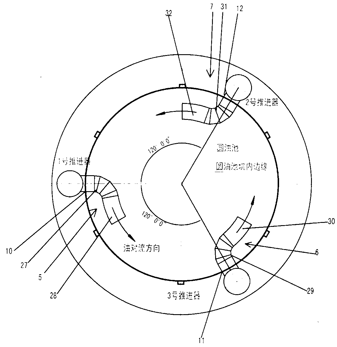
[0025] The pool wall 9 of the quenching oil pool 1 is cylindrical, and three oil outlet holes are arranged equidistantly along the circumferential direction on the upper part of the pool wall 9; the first elbow through holes are opened equidistantly along the circumferential direction on the lower part of the pool wall 9 10. The second elbow through hole 11 and the third elbow through hole 12, the angle between the centers of the first elbow through hole 10, the second elbow through hole 11 and the third elbow through hole 12 is 120° °;

[0026] The first oil thruster comprises oil delivery tube 13, propeller rotating shaft 14, propeller blade 15, upper bearing seat 16, lower bearing ...


PUM


Abstract

The invention relates to a bearing propelled stirring quenching device comprising a quenching oil tank, three oil propellers with a same structure, and three fluid directors with a same structure. The three oil propellers are arranged at the quenching oil tank with same distances along a circumferential direction. The three fluid directors are arranged at the bottom of the quenching oil tank with same distances along a circumferential direction. Directing tubes of the three fluid directors are arranged along a circumferential direction, and are arranged with a 30 DEG elevation angle upward. The oil propellers are assembled by using parts of oil transmission tubes, propeller shafts, propeller blades, cylindrical joints, punched bends, and the like. Oil inlet holes on the upper parts of the oil transmission tubes of the three oil propellers are respectively connected with oil outlet holes on the quenching oil tank through pipelines. Punched bends of the three oil propellers are respectively connected with connection bends of the three fluid directors through three bend through holes at the lower part of the quenching oil tank. With the device provided by the invention, large bearing quenching hardness and hardness uniformity are improved, and bearing quality and bearing service life are improved.

Description

technical field [0001] The invention relates to a bearing quenching device, in particular to a quenching device for extra-large stainless steel bearings. Background technique [0002] Heat treatment is to heat the corresponding metal material to a certain temperature and hold it for a certain period of time and then cool it rapidly to change the internal structure of the metal material and enhance the mechanical properties of the metal material. The heat treatment of super large bearing parts plays a very important role in bearing manufacturing. Because the effective thickness of super large bearings is too large, it far exceeds the hardenability of the material. At the same time, because large bearing rings release a lot of heat during quenching and take a long time , so that the local oil temperature rises faster. The conventional quenching cooling method adopts the method of serial cooling through the crane through the crane. Because the workpiece is too large, the serial...

Claims


Application Information

Patent Timeline
IPC IPC(8): C21D1/64C21D9/40
Inventor 王国增王衍涛范佳明
Owner DALIAN GRANDWAY BEARING
Why Eureka
Try Eureka