Double-effect cooler

A cooler and cooling water technology, applied in the direction of heat exchanger types, indirect heat exchangers, fixed tubular conduit components, etc., can solve the problems of less heat exchange time, large energy consumption, small heat exchange area, etc., and achieve saving Effects of material cost, heat exchange efficiency improvement, and running cost reduction

Inactive Publication Date: 2012-10-31
HANGZHOU DACHAO PETROCHEM EQUIP
View PDF5 Cites 10 Cited by
  • Summary
  • Abstract
  • Description
  • Claims
  • Application Information

AI Technical Summary

Problems solved by technology

[0004] Existing coolers generally use a single-tube, single-layer spiral tube structure to cool down. The disadvantages are: small heat transfer area, short cooling water flow time, short heat transfer time, large volume, and high energy consumption

Method used


Image

  • Double-effect cooler
  • Double-effect cooler

Examples


Embodiment Construction

[0018] Below in conjunction with accompanying drawing and specific embodiment the present invention is described in further detail:

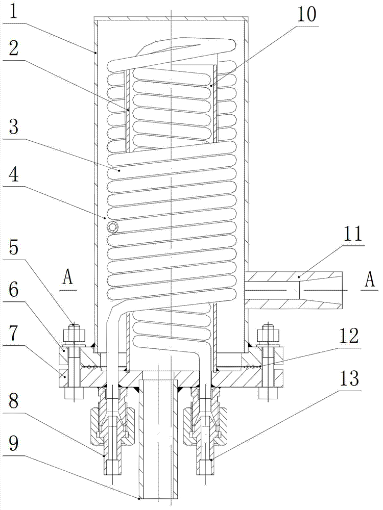
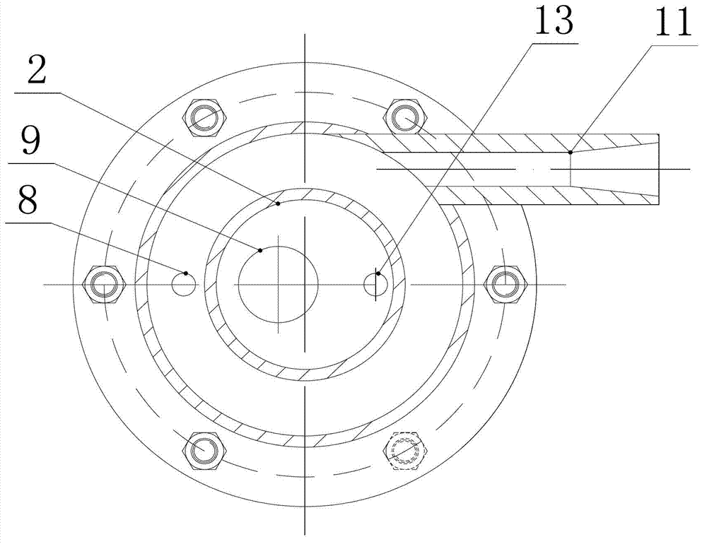
[0019] figure 1 Among them, the double-effect cooler includes an outer cylinder 1 with a closed end and an open end, the outer edge of the open end is provided with an outer cylinder flange 6, and the end cover flange 7 is fixedly connected with the outer cylinder flange 6 through bolts 5; the outer cylinder 1 The cooling water inlet 11 is set on the wall of the end cover flange 7, and the cooling water outlet 9, the sample water outlet 8 and the sample water inlet 13 are arranged on the end cover flange 7, and the sample water outlet 8 and the sample water inlet 13 are respectively connected to the two ends of the double helix coil 3. end.

[0020] The inside of the outer cylinder 1 is provided with an inner cylinder 2, one end of the inner cylinder 2 is not in contact with the inner wall of the closed end of the outer cylinder 1, the other en...


PUM


Abstract

The invention relates to cooling equipment, and discloses a double-effect cooler. The double-effect cooler comprises an outer barrel with a closed end and an open end, wherein an outer barrel flange is arranged on the outer rim of the open end; an end cover flange is fixed on the outer barrel flange through a bolt; a cooling water inlet is formed on the wall of the outer barrel; a cooling water outlet, a sample water outlet and a sample water inlet are formed on the end cover flange; the sample water outlet and the sample water inlet are respectively connected to the two ends of a dual-helix coil pipe; an inner barrel is arranged inside the outer barrel; the dual-helix coil pipe is divided into an outer coil pipe and an inner coil pipe; the inner coil pipe is inserted into the inner barrel; the outer coil pipe is sleeved on the outer side of the inner barrel; the inner coil pipe is connected with the sample water inlet at the end cover flange; the outer coil pipe is connected with the sample water outlet at the end cover flange; and the cooling water outlet is in the range of the inner barrel at the end cover flange. Compared with the conventional single-helix-coil-pipe cooler, the double-effect cooler has the advantages of increasing the heat exchange area, saving the material cost, prolonging the heat exchange time, improving the heat exchange efficiency and reducing the running cost.

Description

technical field [0001] The invention relates to cooling equipment, in particular to a double-effect cooler in a water vapor centralized sampling and analysis device. Background technique [0002] The centralized water vapor sampling and analysis device is a device suitable for centralized water vapor sampling and analysis in steam power plants and steam supply equipment. Its main function is to cool down, depressurize, and constant temperature the high-temperature and high-pressure water vapor samples, and then detect and analyze them with online instruments. . [0003] With the advancement of science and technology, in order to meet the needs of low-carbon environmental protection and sustainable development, steam-powered power plant boilers have gradually shifted from high-pressure boilers to subcritical pressure boilers and supercritical pressure boilers. The pressure and temperature of steam-water samples have also changed from 6-14MPa, 46 -540°C is increased to 17-22M...

Claims


Application Information

Patent Timeline
Patent Type & Authority Applications(China)
IPC IPC(8): F28D7/02
Inventor 杨树东
Owner HANGZHOU DACHAO PETROCHEM EQUIP
Why Eureka
Try Eureka