
Digital display gradienter and machine tool guiding rail leveling method

A leveling and leveling technology, applied in instruments, mapping and navigation, measuring devices, etc., can solve the problems of high price of semiconductor laser collimators, easy accumulation of errors in measurement, and deviation of level beads from the center of the scale, etc. The effect of small precision error and high precision

Active Publication Date: 2014-11-26
齐国崴
View PDF4 Cites 0 Cited by
  • Summary
  • Abstract
  • Description
  • Claims
  • Application Information

AI Technical Summary

Problems solved by technology

[0002] In the prior art, most of the leveling detection of machine tool guide rails uses a frame level. A slight collision or vibration with the guide rail of the machine tool will easily make the horizontal bead deviate from the center of the scale, which makes the measurement prone to cumulative errors
[0003] Using a semiconductor laser collimator to calibrate machine tool guide rails can only measure the straightness within 29 meters, which has a distance limit. In addition, when using it, it is necessary to eliminate uncertain factors such as electromagnetic interference, environmental vibration, dust, and temperature difference. Otherwise, its accuracy will be greatly affected. Furthermore, semiconductor laser collimators are expensive, which is not conducive to controlling production costs.

Method used


Image

  • Digital display gradienter and machine tool guiding rail leveling method
  • Digital display gradienter and machine tool guiding rail leveling method
  • Digital display gradienter and machine tool guiding rail leveling method

Examples


Embodiment Construction

[0036] The technical solutions of the present invention will be described in further detail below through specific implementation methods.

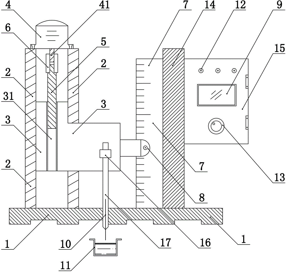
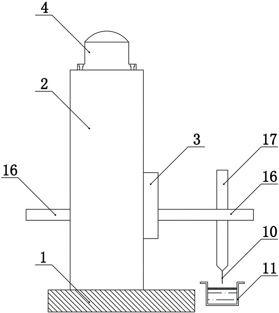
[0037] Such as figure 1 Shown, a kind of digital level, it comprises not less than a level and a water tank 11, that is, one or more level shares a water tank 11, and the same horizontal plane in the water tank 11 is used as a horizontal reference for high-precision simulation.

[0038] The spirit level includes a horizontal base 1, a vertical guide rail 2 arranged on the horizontal base 1, a ball screw 5 vertically arranged in the vertical guide rail 2, and a vertical guide rail 5 arranged in the vertical guide rail 2. To the sliding block 3, the stepping motor 4 installed on the top of the vertical guide rail 2, the stepping motor driver 18 electrically connected with the stepping motor 4, the hand wheel electrically connected with the stepping motor driver 18 13. Digital display grating ruler, conductive wire 10 vertically arranged o...


PUM


Abstract

The invention provides a digital display gradienter and a machine tool guiding rail leveling method. The digital display gradienter comprises a gradienter and a water channel, wherein the gradienter comprises a horizontal base, a vertical guiding rail, a ball screw, a vertical sliding block, a stepping motor, a stepping motor driver, a hand-cranking wheel, a digital display grating ruler, a static wire, an indicating lamp and a working power source. The stepping motor drives the ball screw which drives the vertical sliding block to move vertically. The digital display grating ruler comprises a grating ruler, a grating ruler reading head and a grating ruler displayer. Two ends of the working power source are respectively connected with a water tank and one end of the indicating lamp, the other end of the indicating lamp is connected with the upper end of the static wire, and the lower end of the static wire is arranged corresponding to the water tank. By means of the method, three gradienters simultaneously perform leveling on a machine tool guiding rail, a first gradienter is separately fixed and provides reference coordinates of the plane, and the other two gradienters are respectively placed on a level guiding rail and a V-shaped guiding rail for dynamically testing the relative horizontal degree of the guiding rails. The digital display gradienter is high in accuracy, and leveling through the method is high in efficiency.

Description

technical field [0001] The invention relates to an instrument for measuring the straightness or flatness of mechanical equipment, in particular to a digital display level and a machine tool guide rail leveling method. Background technique [0002] In the prior art, most of the leveling detection of machine tool guide rails uses a frame level. A slight collision or vibration with the guide rail of the machine tool will easily cause the horizontal bead to deviate from the center of the scale, which makes the measurement prone to cumulative errors. [0003] Using a semiconductor laser collimator to calibrate machine tool guide rails can only measure the straightness within 29 meters, which has a distance limit. In addition, when using it, it is necessary to eliminate uncertain factors such as electromagnetic interference, environmental vibration, dust, and temperature difference. Otherwise, its accuracy will be greatly affected. Furthermore, the semiconductor laser collimator ...

Claims


Application Information

Patent Timeline
Patent Type & Authority Patents(China)
IPC IPC(8): G01C9/00
Inventor 齐国崴
Owner 齐国崴
Learn More