
Brushed direct-current motor

A technology of brushed DC motors and brushes, applied in DC commutators, DC interrupters, circuits, etc., can solve problems such as poor mechanical properties and unsuitable strength for use, and achieve low cost, simple structure, and firm structure Effect

Inactive Publication Date: 2012-10-31
JOHNSON ELECTRIC SHENZHEN
View PDF7 Cites 2 Cited by
  • Summary
  • Abstract
  • Description
  • Claims
  • Application Information

AI Technical Summary

Problems solved by technology

[0003] However, in this brushed DC motor, the winding is arranged on the rotor, and the rotor winding rotates at a high speed, so the mechanical characteristics are poor; moreover, the winding usually uses copper wire, which is not suitable for using weaker wires such as aluminum wire

Method used


Image

  • Brushed direct-current motor
  • Brushed direct-current motor
  • Brushed direct-current motor

Examples


Embodiment Construction

[0026] The technical solutions and other beneficial effects of the present invention will be apparent through the detailed description of specific embodiments of the present invention below in conjunction with the accompanying drawings.

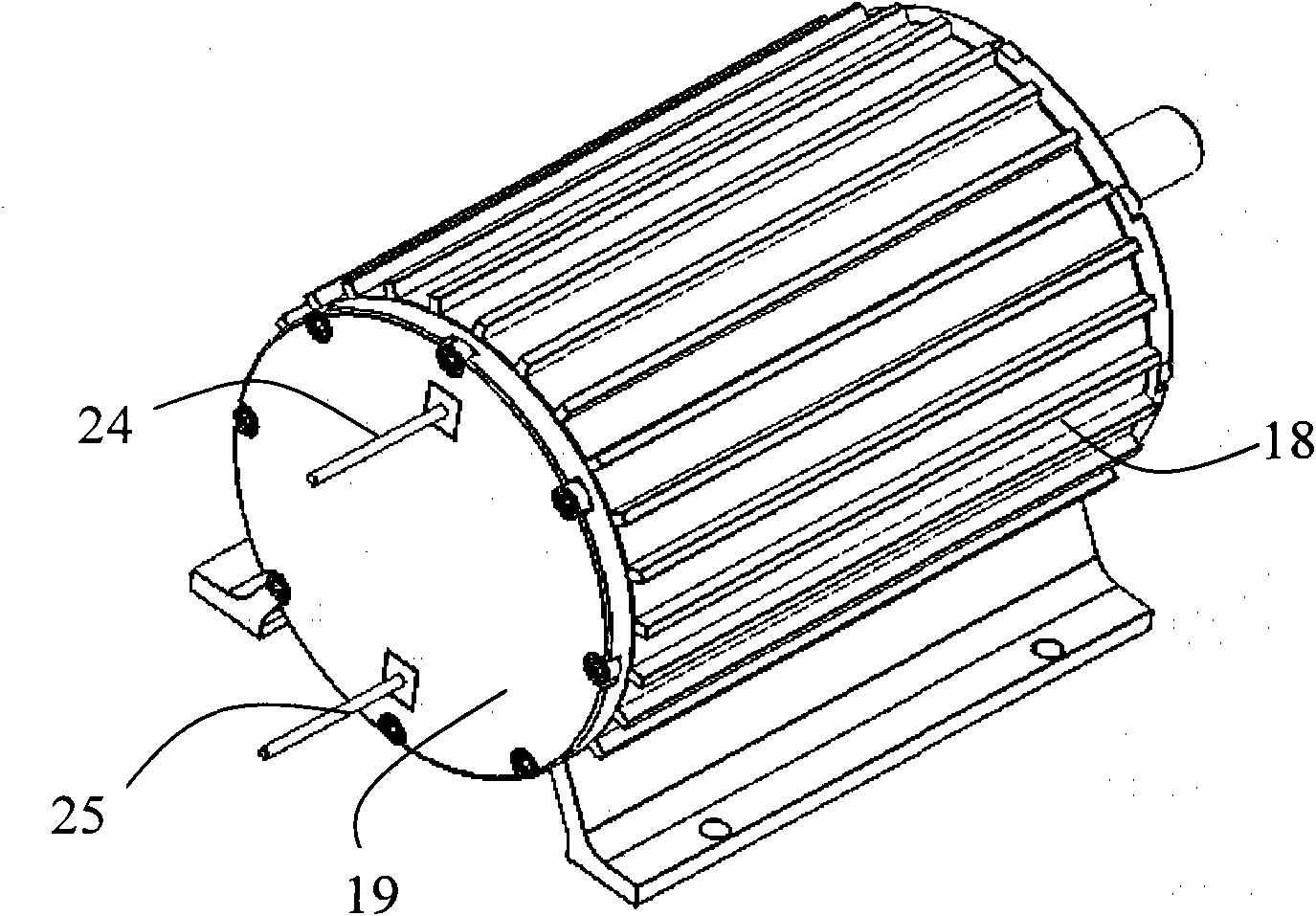
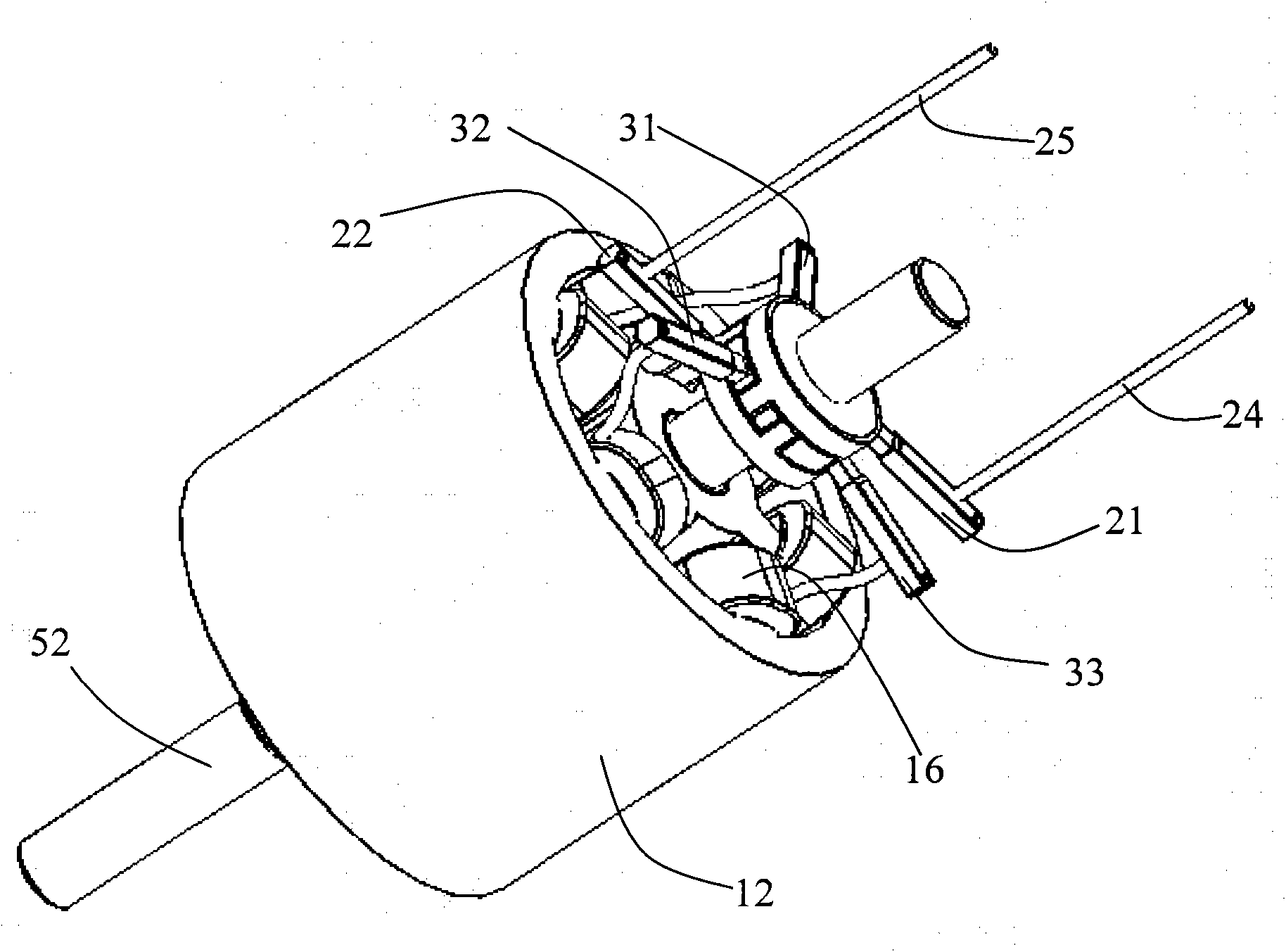
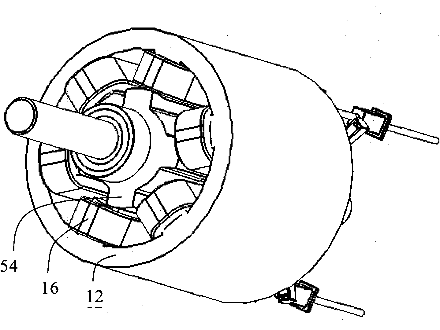
[0027] see Figure 1 to Figure 5 , a brushed DC motor according to an embodiment of the present invention includes a stator and a rotor rotatable relative to the stator.

[0028] The stator includes an annular iron core 12 made of magnetically permeable material, and several windings 16 wound on the inwardly extending stator salient poles 14 of the iron core 12. In this embodiment, the windings 16 are concentrated windings ( That is, each winding 16 is only wound on one salient pole 14), the stator is provided with six salient poles 14, winding slots are formed between adjacent salient poles 14, and a winding is wound on each salient pole 14, thereby forming 6 windings 16. Preferably, the winding 16 is wound by aluminum wires, of course, ot...


PUM


Abstract

The invention relates to a brushed direct-current motor, which comprises a stator and a rotor. The stator comprises a plurality of windings and a stator magnetically-conductive salient pole core. The rotor comprises a rotor magnetically-conductive salient pole core and two mutually insulated reversing devices, wherein each reversing device comprises electrically-conductive parts and a plurality of reversing parts. The stator further comprises two first electric brushes and a plurality of second electric brushes, wherein the first electric brushes are connected with one electrode of a power supply through a select switch and is in sliding contact with the two electrically-conductive parts respectively; the second electric brushes are connected with the windings respectively; the other end of each winding is connected with the other electrode of the power supply; the select switch selectively conducts one of the two first electric brushes to one electrode of the power supply, so that the motor can rotate in one of two opposite directions; and the second electric brushes are in sliding contact with the reversing parts so as to alternately provide single-polarity electric excitation for each winding. According to the brushed direct-current motor provided by the invention, the windings are arranged on the stator and no magnet is arranged on the rotor, so that the brushed direct-current motor is firm; and the windings adopt a single-polarity excitation mode, so that fewer electric brushes are needed and the reversing devices have simple structures.

Description

technical field [0001] The invention relates to a brushed motor, in particular to a brushed DC motor. Background technique [0002] In the existing brushed DC motor, the rotor usually includes a commutator and a winding electrically connected to the commutator, the stator usually includes a permanent magnet opposite to the rotor winding and a brush in sliding contact with the commutator, and the winding passes through the commutator and brushes are connected to the power supply. [0003] However, in this brushed DC motor, the winding is arranged on the rotor, and the rotor winding rotates at a high speed, so the mechanical characteristics are poor; moreover, the winding usually uses copper wire, which is not suitable for using a wire with poor strength such as aluminum wire. [0004] The invention aims to provide a novel brushed DC motor with static winding, no magnet salient core and rotating rotor. Contents of the invention [0005] The invention provides a brushed dir...

Claims


Application Information

Patent Timeline
Patent Type & Authority Applications(China)
IPC IPC(8): H02K23/02H02K1/14H02K1/24
CPCH01R39/04H02K25/00H02K23/36H02K23/00H02K23/20H02K13/00H02K23/18H02K13/006H02K13/04
Inventor 李越刘力生戚永清张洪建
Owner JOHNSON ELECTRIC SHENZHEN
Learn More