
Low-consumption optical module, and realization method and realization circuit thereof

An implementation method and technology of optical modules, applied in the field of optical communication, can solve the problems of failing to meet the requirements of low power consumption, increasing the cost of optical modules, weakening competitiveness, etc., to increase the competitiveness of products, meet the requirements of low power consumption, reduce cost effect

Inactive Publication Date: 2012-10-31
HISENSE BROADBAND MULTIMEDIA TECH
View PDF4 Cites 3 Cited by
  • Summary
  • Abstract
  • Description
  • Claims
  • Application Information

AI Technical Summary

Problems solved by technology

This method of reducing power consumption of optical modules has the following defects: First, it is very dependent on the technology and performance of integrated chips and optical device components, and is very dependent on the investment and support of integrated chip suppliers and optical device suppliers for low-power products; The second is that such chips and laser components are more expensive, which increases the cost of optical modules, thereby weakening the competitiveness of products; moreover, after adopting low-power integrated chips and laser components with high slope rate and high coupling efficiency , but still fail to meet the low power consumption requirements of equipment manufacturers, this method of reducing power consumption of optical modules will immediately enter a dead end, and it will appear powerless in the face of customers' low power consumption requirements

Method used


Image

  • Low-consumption optical module, and realization method and realization circuit thereof
  • Low-consumption optical module, and realization method and realization circuit thereof
  • Low-consumption optical module, and realization method and realization circuit thereof

Examples


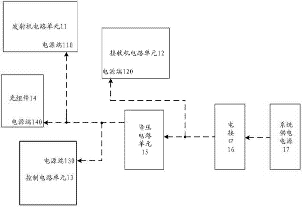
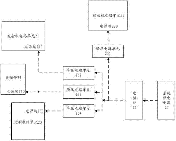
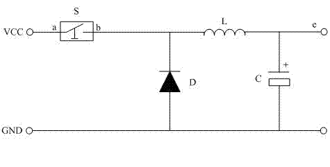
Embodiment Construction

[0026] Specific embodiments of the present invention will be described in detail below in conjunction with the accompanying drawings.

[0027] First, briefly explain the starting point of the technical design of the present invention: the functional circuit units in the existing optical modules are generally implemented by integrated chips, and in the electrical characteristics of the integrated chips, a wider voltage is generally marked for the power supply voltage Voltage range, within which the integrated chip can work normally. If the supply voltage of the chip is lower, its power consumption will be lower.

[0028] Combining this feature, the present invention proposes a method for realizing a low-power consumption optical module. Specifically, first read the output voltage of the system power supply that supplies power to the optical module; then, reduce the output voltage to a low voltage that is allowed for the normal operation of the functional circuit unit of the op...


PUM


Abstract

The invention discloses a low-consumption optical module, and a realization method and a realization circuit thereof. The realization method comprises the following steps: reading output voltage of a system power supply which powers the optical module; reducing the output voltage into a low voltage which is required to ensure the normal operation of a function circuit unit of the optical module; and sending the low voltage as the supply voltage to the corresponding function circuit unit. The realization method has the advantages of simplicity and low cost, and is easy to apply in the optical module.

Description

technical field [0001] The present invention relates to the technical field of optical communication, in particular to an optical module with low power consumption, and more specifically to a method for realizing the optical module with low power consumption, a realization circuit and the optical module. Background technique [0002] In recent years, the development of optical modules has become more and more rapid, and the trend of low power consumption and miniaturization requirements for optical modules has become more and more obvious. The size of equipment manufacturers' communication equipment is getting smaller and smaller, and the density of interfaces contained in interface boards is getting higher and higher, all of which require optical modules to develop in the direction of low power consumption and miniaturization. For example, for SFP+ LR optical modules, equipment manufacturers generally require their power consumption to be within 1W, and some equipment manuf...

Claims


Application Information

Patent Timeline
IPC IPC(8): H04B10/00G02B6/42
Inventor 赵平张华吴锡贵王三
Owner HISENSE BROADBAND MULTIMEDIA TECH
Learn More