Double-base-island chip driving circuit, chip, constant-current driving circuit and control method

A driving circuit and chip technology, applied in electrical components and other directions, can solve the problems of wide power supply voltage range and high efficiency, and achieve the effect of power expansion, high power supply efficiency, and guaranteed stability

Pending Publication Date: 2021-07-23
SHANGHAI LOOALL ELECTRONICS CO LTD
View PDF11 Cites 0 Cited by
  • Summary
  • Abstract
  • Description
  • Claims
  • Application Information

AI Technical Summary

Problems solved by technology

[0006] The technical problem to be solved by the present invention is to overcome the defect that the linear constant current drive circuit for LED lighting in the prior art cannot meet the wide range of power supply voltage and high efficiency at the same time, and provide a dual base island chip drive circuit, chip, constant current Driving circuit and control method

Method used


Image

  • Double-base-island chip driving circuit, chip, constant-current driving circuit and control method
  • Double-base-island chip driving circuit, chip, constant-current driving circuit and control method
  • Double-base-island chip driving circuit, chip, constant-current driving circuit and control method

Examples


Embodiment 1

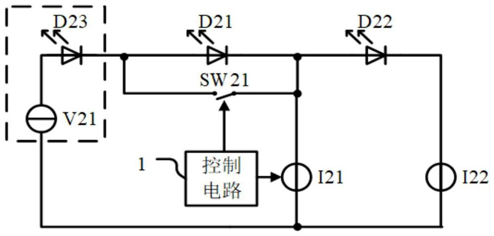
[0065] This embodiment provides a linear constant current drive circuit, and the load is represented by LEDs, such as figure 2 As shown, the linear constant current drive circuit includes a power supply V21, a first LED D21, a second LED D22, a first current source I21, a second current source I22, a switch SW21 and a control circuit 1, a power supply V21, a first LED D21, the second LED D22 and the second current source I22 are sequentially connected in series to form a closed loop; the switch SW21 is connected in parallel to both ends of the first LED D21; one end of the first current source I21 is connected to the first LED D21 and the second LED D22. intersection point, the other end is connected to the intersection point of the second current source I22 and the power supply V21; the control circuit 1 is respectively connected to the switching switch SW21 and the first current source I21 for controlling the conduction of the switching switch SW21 and the first current sour...

Embodiment 2

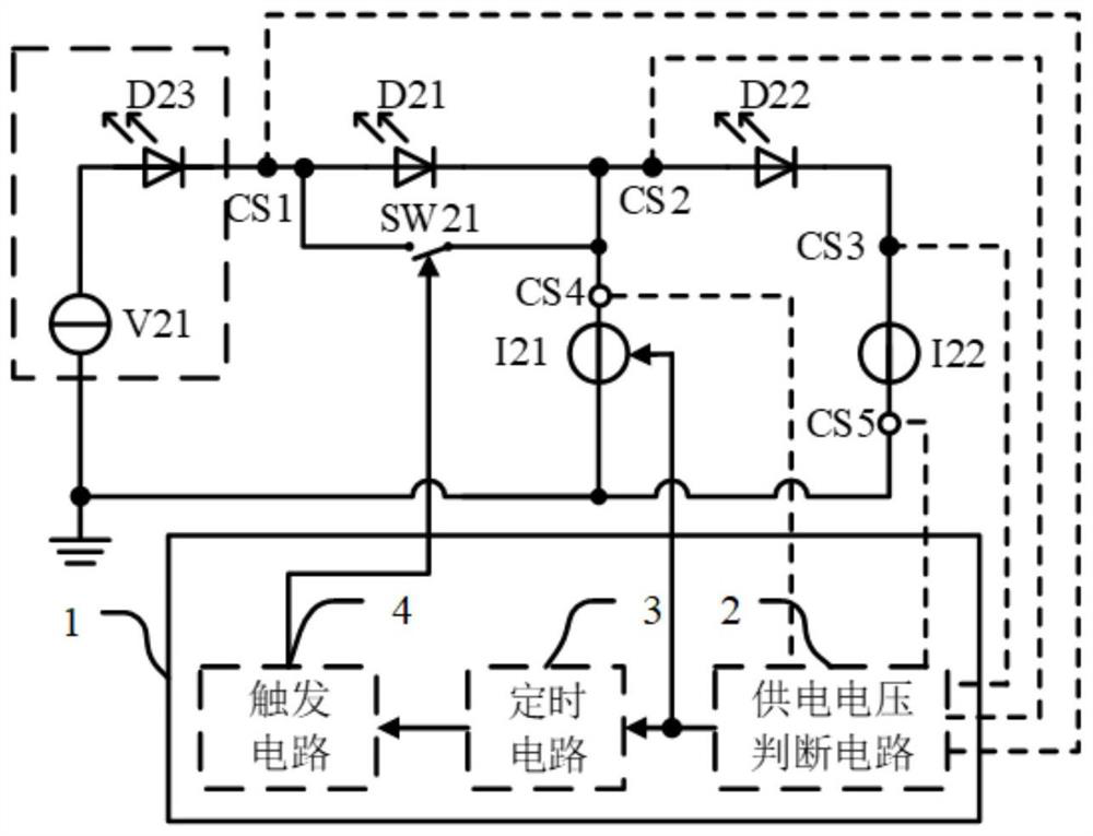
[0076] This embodiment refines the control circuit on the basis of Embodiment 1. Such as image 3 As shown, the control circuit 1 includes a power supply voltage judging circuit 2 , a timing circuit 3 and a trigger circuit 4 . Obviously, in practical applications, the corresponding control circuit can be integrated as required, and the switch can also be integrated, or a part of them can be integrated, packaged as one or more chips, connected with the corresponding peripheral LED and power supply through pins, and controlled The opening or closing of the corresponding channel.

[0077] The power supply voltage judging circuit 2 detects the voltage at both ends of the power supply V21 (i.e. image 3 middle detection point CS1), the voltage across the first current source I21 (ie image 3 middle detection point CS2) or the voltage across the second current source I22 (ie image 3 One or more of the middle detection point CS3), or detect the flow through the first current sou...

Embodiment 3

[0080] The power supply voltage judging circuit 2, the timing circuit 3 and the trigger circuit 4 in the second embodiment can be implemented in many ways, and this embodiment is only one of them, and those skilled in the art should know that there are many different ways Other implementation forms departing from the scope of the present invention, this embodiment will image 3 The corresponding power supply voltage judging circuit 2, timing circuit 3 and trigger circuit 4 are further detailed, and at the same time, the working process of the linear constant current driving circuit is specifically described by taking the detection of the current flowing through the second current source I22 as an example. Such as Figure 4 As shown, the power supply voltage judgment circuit 2 of this embodiment includes a signal detection circuit JC1, a first comparison circuit and a first preset signal reference V T1 , where the first comparison circuit is the first comparator A1.

[0081] ...


PUM


Abstract

The invention discloses a double-base-island chip driving circuit, a chip, a constant-current driving circuit and a control method. The double-base-island chip driving circuit comprises a first current source, a second current source, a change-over switch and a control circuit, wherein one ends of the first current source and the second current source are mutually connected, and the other ends are respectively connected with the outside; the control circuit is used for detecting current or voltage parameters in the circuit and controlling the switching-on or switching-off of the change-over switch and the first current source; the first current source, the second current source and the control circuit are arranged on a carrier; two ends of the change-over switch control opening or closing of an access formed by connection of two external ends, and the change-over switch is arranged on the other carrier. Through the arrangement of the double base islands, chips are integrated, stable and efficient power supply is provided for an LED device, chip cascading is facilitated, high-power driving support can be provided, the adaptable power supply voltage range is wide, and the power supply efficiency is high.

Description

[0001] This application claims the priority of the Chinese patent application CN201910493482.1 with the filing date of June 6, 2019. [0002] This application claims the priority of the Chinese patent application CN201911107801.7 with the filing date of November 13, 2019. [0003] This application cites the full text of the above-mentioned Chinese patent application. technical field [0004] The invention relates to the field of LED drive circuits, in particular to a double base island chip drive circuit, a chip, a constant current drive circuit and a control method. Background technique [0005] Current LED lighting generally uses a linear constant current drive circuit, such as figure 1 As shown, the power supply V11, the LED device D11 and the current source I11 are serially connected in sequence to form a closed energy loop. The circuit is very simple, but the voltages of the power supply V11 and the LED device D11 are required to be as close as possible to obtain high...

Claims


Application Information

Patent Timeline
Patent Type & Authority Applications(China)
IPC IPC(8): H05B45/345H05B45/30H05B45/10
CPCH05B45/345H05B45/30H05B45/10
Inventor 邵蕴奇徐勇
Owner SHANGHAI LOOALL ELECTRONICS CO LTD
Why Eureka
Try Eureka