Electronic system and power-on and power-off state detection circuit therefor

A technology for detecting circuits and electronic systems, applied in the direction of electronic switches, logic circuits, logic circuit connection/interface layout, etc., can solve problems such as functional defects, undetectable, and inability to effectively detect the power-off state of the main circuit, and achieve effective Detection effect

Inactive Publication Date: 2018-10-16
SEMICON MFG INT (SHANGHAI) CORP +1
View PDF16 Cites 0 Cited by
  • Summary
  • Abstract
  • Description
  • Claims
  • Application Information

AI Technical Summary

Problems solved by technology

[0004] In the prior art, there is a circuit that uses a high-level selection method to detect the power-on and power-off of the main circuit and the IO interface circuit. This circuit can detect whether the main circuit is powered on after the IO interface circuit of the integrated circuit is powered on. power-on, however, when the main circuit is powered-on and then powered off, it cannot be detected
[0005] Therefore, the power-on and power-off state detection circuits in the prior art have functional defects, and cannot effectively detect the power-off state of the main circuit

Method used


Image

  • Electronic system and power-on and power-off state detection circuit therefor
  • Electronic system and power-on and power-off state detection circuit therefor
  • Electronic system and power-on and power-off state detection circuit therefor

Examples


Embodiment Construction

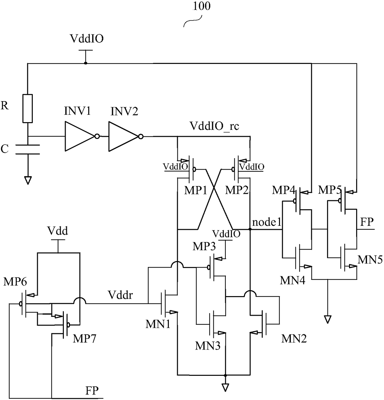
[0034] As mentioned in the background section, figure 1 The power-on and power-off state detection circuit shown can only detect the power-on of the main circuit, but cannot detect the power-off of the main circuit. It has functional defects and cannot take into account the power-on and power-off of the main circuit and the IO interface circuit. Valid detection of state.

[0035] figure 1 A power-on and power-off state detection circuit 100 is shown. Such as figure 1 As shown, the power-on and power-off state detection circuit 100 may include: resistor R, capacitor C, inverters INV1 and INV2, PMOS transistors MP1, MP2, MP3, MP4, MP5, MP6 and MP7, NMOS transistors MN1, MN2 , MN3, MN4, and MN5. When the power supply voltage VddIO of the IO interface circuit (not shown in the figure) is established and the power supply voltage Vdd of the main circuit (not shown in the figure) is not established, the detection signal FP output by the output terminal of the power-on and power-o...


PUM


Abstract

The invention discloses an electronic system and a power-on and power-off state detection circuit therefor. The electronic system includes a main circuit and an IO interface circuit, and the power-onand power-off state detection circuit comprises a first level converting circuit, wherein the power voltage of the main circuit is inputted into the first input end of the first level converting circuit, and the power voltage of the IO interface circuit is inputted into the second input end of the first level converting circuit. The first level converting circuit is suitable for the level conversion of the power voltage of the main circuit to generate a power-on and power-off detection signal, wherein the power-on and power-off detection signal is within a power domain defined by the power voltage of the IO interface circuit. According to the scheme of the invention, the system can effectively detect the power-on states of the main circuit and the IO interface circuit and also can effectively detect the power-off state of the main circuit. Moreover, the system is lower in leaked current, is wider in power voltage application range, and is smaller in circuit area.

Description

technical field [0001] The invention relates to the field of electronic circuit design, in particular to an electronic system and a power-on and power-off state detection circuit thereof. Background technique [0002] In an integrated circuit (Integrated Circuit, IC for short), it may generally include at least two circuit domains, a main circuit and an IO (Input / Output) interface circuit. Wherein, the main circuit may include other functional circuits other than the IO interface circuit, generally referred to as a core circuit, and may also be referred to as an intellectual property (Intellectual Property, referred to as IP) core. [0003] Take the main circuit as an IP core as an example. The IO interface circuit has input / output bidirectional ports. Inside the chip, the IP core can send data signals to the IO interface circuit for signal output, and can also receive data signals input by the IO interface circuit for reading. Generally speaking, the IP core and the IO i...

Claims


Application Information

Patent Timeline
Patent Type & Authority Applications(China)
IPC IPC(8): H03K19/0185H03K17/687
CPCH03K17/687H03K19/018507
Inventor 耿彦陈捷马晓媛朱恺尚超华
Owner SEMICON MFG INT (SHANGHAI) CORP
Why Eureka
Try Eureka