Big-thickness slab manufacturing technique

A manufacturing process and large thickness technology, applied in manufacturing tools, workpiece edge parts, metal processing equipment, etc., can solve the problems of complex operation, high production cost, low production efficiency, etc., to improve production efficiency, improve welding efficiency, high efficiency production effect

Inactive Publication Date: 2012-11-07
JIGANG GRP
View PDF12 Cites 15 Cited by
  • Summary
  • Abstract
  • Description
  • Claims
  • Application Information

AI Technical Summary

Benefits of technology

The present inventors describe an improvement technique called Gas Welding: By utilizing multiple different techniques such as gas shield weldings, submersible arc wires, and laser scanning, they aim towards producing ultra thin slabs while maintaining good quality standards. They also consider optimizing the winding sequences and methods based upon factors like energy input rate, coolant flow rates, and pressure levels. Overall, their innovations help achieve higher productivity and lower production costs through optimized weld procedures.

Problems solved by technology

Technological Problem: Current Gas Shielded Arc Fusion Wide Castings (SCFW), particularly those made from materials like titanium alloys, require expensive facilities and involve challenging procedures involving assembly processes requiring skilled workers. Additionally, these techniques result in poor productivity rates and increased operating expenses compared to other technologies.

Method used


Image

  • Big-thickness slab manufacturing technique
  • Big-thickness slab manufacturing technique
  • Big-thickness slab manufacturing technique

Examples


Embodiment 1

[0029] Embodiment 1: Production of 180mm thick Q345B steel plate

[0030] 1) Process two 300mm thick Q345B continuous casting slabs by milling machine to remove surface oxide scale, oil stains, etc. to achieve surface cleanliness, and process the two slabs to the same size.

[0031] 2) The three sides of the surface-processed continuous casting slab to be welded are processed by flame cutting method, the groove depth is 25mm, and the groove angle is 30°.

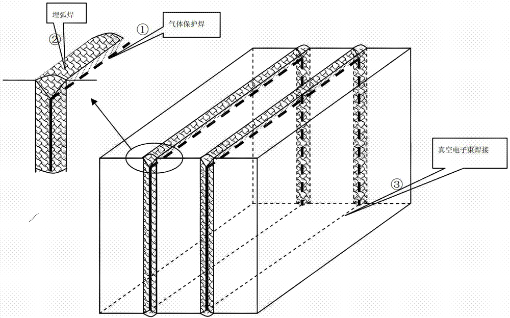
[0032] 3) After the processed continuous casting slabs are stacked together, they are rotated 90° and placed vertically, aligned and clamped.

[0033] 4) Adopt the welding method of gas shielded welding to carry out bottom welding on the edge seams of the three sides of the continuous casting slab that have processed the groove, the diameter of the welding wire is 2.0mm, the welding voltage is 20V, the welding current is 200A, and the welding speed is 300mm / min , the dry elongation of the welding wire is 25mm, and the shieldi...

Embodiment 2

[0045] Embodiment 2: Production of 400mm thick Q345B extra thick steel plate

[0046] 1) Process the produced three 300mm thick Q345B continuous casting slabs with a milling machine to remove surface oxide scales, oil stains, etc. to clean the surface and process them into the same size.

[0047] 2) The three sides of the surface-processed continuous casting slab to be welded are processed by flame cutting method, the groove depth is 30mm, and the groove angle is 30°.

[0048] 3) After the processed blanks are stacked together, they are rotated 90° and placed vertically, aligned and clamped.

[0049] 4) Adopt the welding method of gas shielded welding, and perform bottom welding on the six side seams with processed grooves on the three sides of the blank. The diameter of the welding wire is 2.0mm, the welding voltage is 20V, the welding current is 200A, the welding speed is 500mm / min, and the welding wire The dry elongation is 25mm, and the protective gas is CO 2 , the prote...


PUM

PropertyMeasurementUnit
Thicknessaaaaaaaaaa

Abstract

The invention discloses a big-thickness slab manufacturing technique belonging to the technical field of ferrous metallurgy. According to the technique, more than two continuous casting slab blanks are overlapped, and then the four sides of the blanks are combined and welded by using a combined welding technique of gas shielded welding, submerged-arc welding and electron-bombardment welding so as to form one big-thickness slab. The invention breaks through the limit of complex manufacturing process, no guarantee in inner quality or low production efficiency in the traditional big-thickness slab manufacturing technique and provides a method for producing a big-thickness slab with high quality and high efficiency by using the traditional continuous cast slab blanks, and the method is simple in operation, small in investment, high in production efficiency, flexible in organization form, capable of well satisfying the requirement of a raw material used for producing the big-thickness slab with high piece weight and high compression ratio and realizing mass industrial production, and especially suitable for the production of the big-thickness slab with the thickness of more than 600mm, and is widely applied to the manufacturing of high-quality super-thick steel plates used for various important technique equipment.

Description


Claims


Application Information

Patent Timeline
Owner JIGANG GRP
Why Eureka
Try Eureka