Transformer coil lifting beam

A technology of transformer coils and hanging beams, which is applied in the direction of load hanging components, transportation and packaging, etc. It can solve the problems of insufficient storage space, cost waste, and non-universal use of special iron pressure rings, so as to enhance versatility, reduce costs, and avoid The effect of partial discharge

Inactive Publication Date: 2012-11-07
SHANDONG POWER EQUIP
View PDF5 Cites 4 Cited by
  • Summary
  • Abstract
  • Description
  • Claims
  • Application Information

AI Technical Summary

Problems solved by technology

The reason why the special iron pressure ring is "special" is because it needs to be made according to the inner diameter of each coil. A transformer needs to use up to 30 pieces of special iron pressure rings and 90 screws. Making special iron pressing rings and storing a large number of special iron pressing rings has brought a lot of trouble, but it is the key device for coil demoulding and is indispensable
[0003] The disadvantage of this method is that the special iron pressure ring is used in a large amount, each is different, the production workload is very large, the equipment limitation and the processing cost are high; the second is that the special iron pressure ring is not universal, and the used special iron The pressure ring needs to be stored for rectification and use. If things go on like this, the storage space is insufficient, and it is inconvenient to find during the rectification; the third is that some special iron pressure rings cannot be rectified, so they have to be scrapped, resulting in waste of cost; Fastening the coil with the iron pressure ring is time-consuming and labor-intensive

Method used


Image

  • Transformer coil lifting beam
  • Transformer coil lifting beam
  • Transformer coil lifting beam

Examples


Embodiment Construction

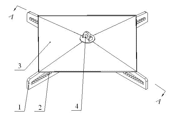
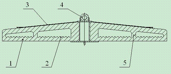
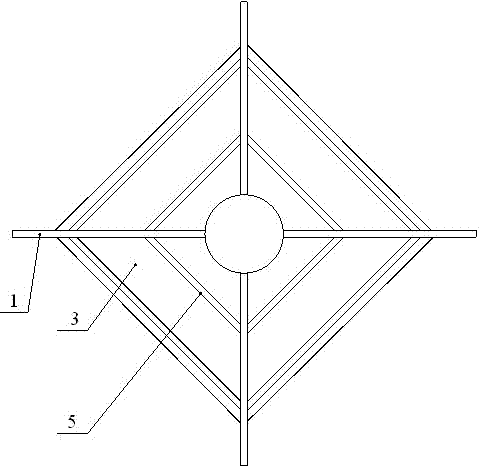
[0016] As shown in the figure, this embodiment includes four booms 1 perpendicular to each other, and the inner ends of the booms 1 are connected to each other. The middle parts of two adjacent booms 1 are connected to each other through a strengthening mechanism 5 . Each boom 1, strengthening mechanism 5 and hanging climb 4 can also adopt an integral structure. Each boom 1 is provided with two holes along its length, and the two holes are bounded by the strengthening mechanism 5 . The bottom edge of each hole is provided with a group of positioning grooves 2 along the length direction of the boom 1, so that the bottom edge forms a similar sawtooth shape.

[0017] A top cover 3 is arranged above the four booms 1 , and a suspension climber 4 is located above the top cover 3 .


PUM


Abstract

The invention discloses a transformer coil lifting beam, and particularly relates to a lifting mechanism for demoulding of a transformer. The transformer coil hanging beam comprises at least three mutually connected radial lifting arms, wherein a group of suspension positioning mechanisms are arranged on each lifting arm in the length direction and a lifting hook is arranged above each lifting arm. The lifting arms of the lifting beam have a certain adjustable range and can be used for the demoulding of transformer coils with different outer diameters, so that the commonality of the lifting beam is enhanced and the cost is reduced. Moreover, the structure of a top cover can meet the purification requirement, so that fallen metal chips or other foreign matters due to wear in running can be effectively prevented from being in contact with the coils and are convenient for users to clean regularly, and local discharge of the transformer due to the foreign matters is avoided at the same time.

Description

technical field [0001] The invention relates to a transformer coil hanging beam, in particular to a lifting mechanism for transformer coil demoulding. Background technique [0002] For a period of time, after the coil of the oil-immersed transformer has been wound on the mold, it usually uses a special iron pressure ring, screw and steel wire rope to cooperate with the demoulding process. The specific method is: use a screw and a special pressure ring to fasten the coil into a whole, and then use a crane and a wire rope to demould. The reason why the special iron pressure ring is "special" is because it needs to be made according to the inner diameter of each coil. A transformer needs to use up to 30 pieces of special iron pressure rings and 90 screws. Making special iron pressing rings and storing a large number of special iron pressing rings has brought a lot of trouble, but it is the key device for coil demoulding and is indispensable. [0003] The disadvantage of this ...

Claims


Application Information

Patent Timeline
Patent Type & Authority Applications(China)
IPC IPC(8): B66C1/10
Inventor 谢辉王士强杨振元
Owner SHANDONG POWER EQUIP
Why Eureka
Try Eureka