Temperature measurement optical fiber adaption module and transformer with temperature measurement optical fiber adaption module

A temperature-measuring optical fiber and transformer technology, which is applied in the field of temperature-measuring optical fiber transfer modules and transformers with temperature-measuring optical fiber transfer modules, can solve the optical loss of three-section optical fiber structure, cannot be used repeatedly, and low coupling efficiency problem, achieve the effect of improving bidirectional optical coupling efficiency, improving signal strength and stability, and good sealing

Active Publication Date: 2021-04-09
西安和其光电科技股份有限公司
View PDF7 Cites 4 Cited by
  • Summary
  • Abstract
  • Description
  • Claims
  • Application Information

AI Technical Summary

Problems solved by technology

[0007] In order to solve the technical problem that the existing two-section optical fiber structure used in oil-immersed transformers has poor sealing performance and cannot be used repeatedly; or the three-section optical fiber structure has optical loss, which makes the coupling efficiency low. Temperature fiber optic transition module and transformer with temperature measurement fiber optic transition module

Method used


Image

  • Temperature measurement optical fiber adaption module and transformer with temperature measurement optical fiber adaption module
  • Temperature measurement optical fiber adaption module and transformer with temperature measurement optical fiber adaption module
  • Temperature measurement optical fiber adaption module and transformer with temperature measurement optical fiber adaption module

Examples


Embodiment 2

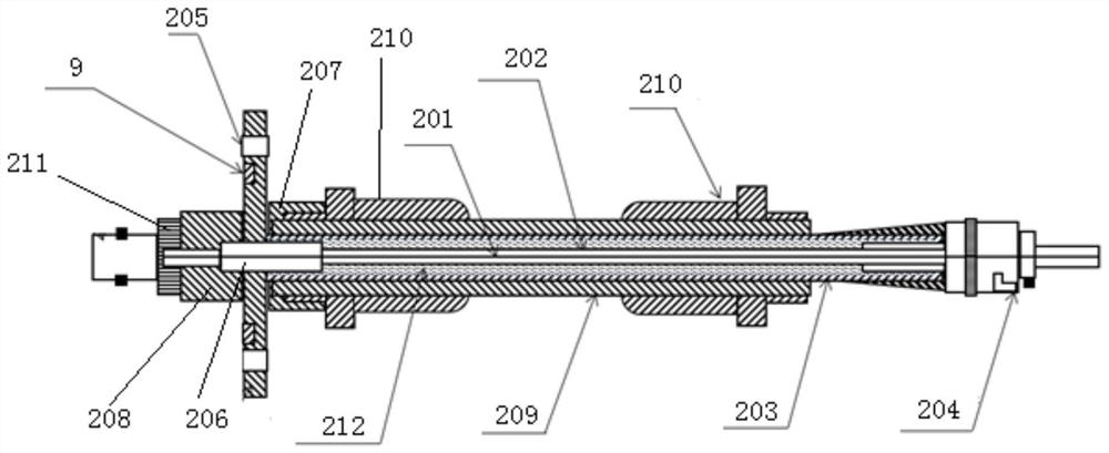
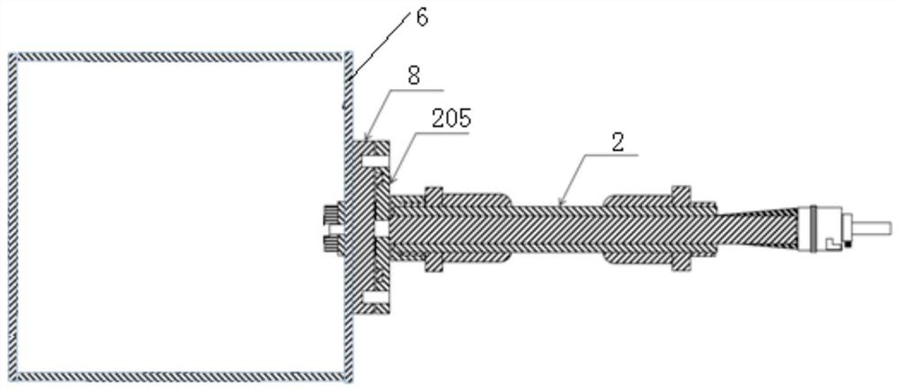
[0071] The difference from Embodiment 1 is that: Figure 4 As shown, the temperature measuring probe 1 is set in the transformer body 6; Figure 5 As shown, the temperature measuring probe 1 includes a temperature measuring optical fiber 11, a first optical fiber inner sheath 12, a first optical fiber outer sheath 13, a sheath pressure ring 14 and a first optical fiber connector 15; the first optical fiber outer sheath 13 is set on On the first optical fiber inner sheath 12, one end of the first optical fiber outer sheath 13 is set in the first optical fiber joint 15 through the sheath pressure ring 14; one end of the temperature measuring optical fiber 11 is bonded with a fluorescent material 16, and the other end passes through The first optical fiber connector 15 is docked with the adapter optical fiber 201, Figure 4 Among them, A is the docking point.

[0072] In this embodiment, the temperature-measuring optical fiber 11 is made of quartz fiber material, the detection ...


PUM


Abstract

The invention provides a temperature measurement optical fiber adaption module and a transformer with the temperature measurement optical fiber adaption module and aims to solve the problems that an optical fiber structure for an existing oil-immersed transformer is poor in sealing performance, cannot be repeatedly plugged and unplugged for use and is low in coupling efficiency are solved. The adaption module comprises a through flange, a coupling joint, two waterproof joints and an adaption optical fiber assembly; the through flange comprises a flange plate, an inner side threaded connector and an outer side threaded connector; the coupling joint is in threaded connection with the inner side threaded connector; the adaption optical fiber assembly comprises a second optical fiber joint, an insertion core, an adaption optical fiber, a second optical fiber inner sheath and a second optical fiber outer sheath; one end of the second optical fiber outer sheath is connected with the second optical fiber joint, and the other end of the second optical fiber outer sheath is arranged in the outer threaded connector; one of the waterproof joints is in threaded connection with the outer side threaded connector; one end of the insertion core is inserted into the coupling joint and is glued with the coupling joint, and the other end of the insertion core is connected with the second optical fiber inner sheath. and one end of the adaption optical fiber is connected with a thermometer, the other end of the adaption optical fiber is inserted in the insertion core and is glued to the insertion core;.

Description

technical field [0001] The invention relates to an optical fiber temperature measurement technology, in particular to a temperature measurement optical fiber transfer module and a transformer with a temperature measurement optical fiber transfer module. Background technique [0002] Oil-immersed transformer is the key equipment of power distribution system. Oil-immersed transformers work in a high-voltage, high-current, and strong magnetic field environment for a long time, and will continue to generate heat during operation. For every 6°C increase in transformer temperature, the aging speed of the transformer doubles and the working life is halved. The safe operation and service life of oil-immersed transformers depend on the safety and reliability of windings, so accurate measurement of transformer winding temperature is particularly important for transformer service life. [0003] For oil-immersed transformers, the optical fiber temperature measurement method is used. W...

Claims


Application Information

Patent Timeline
Patent Type & Authority Applications(China)
IPC IPC(8): G02B6/38G01K11/32
CPCG02B6/3849G02B6/3861G02B6/389G02B6/3823G01K11/32
Inventor 张文松王攀
Owner 西安和其光电科技股份有限公司
Why Eureka
Try Eureka