Multiphase flow regulation device and method for restraining slug flow by utilizing same

A flow adjustment and multiphase flow technology, which is applied in the fields of production fluids, earthwork drilling, drilling equipment, etc., can solve the problems of constant underwater installation and maintenance, limited bending radius, and difficulty in stable placement, and achieves reasonable device structure and implementation. Simple, versatile effects

Active Publication Date: 2012-11-07
青岛红嘴鸟科技有限公司
View PDF14 Cites 9 Cited by
  • Summary
  • Abstract
  • Description
  • Claims
  • Application Information

AI Technical Summary

Problems solved by technology

However, the complexity and diversity of oil and gas product components put forward high requirements for the scope of application of multiphase pumps, and the installation and maintenance process of multiphase pumps and other equipment is complicated
A single-phase pump is used to suck the liquid plug at the top of the standpipe, and it is difficult to ensure that the single-phase pump sucks the pure liquid plug
Chinese patent CN1297778C discloses a separator and a phase-separated conveying method using it to eliminate severe slug flow, but there is also the problem that the underwater installation and maintenance remain unchanged, and it is difficult to ensure that the single-phase pump sucks pure liquid plug
In 2000, the annual meeting of American Petroleum Engineers (document number: SPE63185) released two schemes of self-supplied gas lift method, but there are practical difficulties in the application of these two schemes
The working principle is to adjust the gas-liquid stratified flow to other flow patterns. The device can mix the gas-liquid two-phase flow and temporarily convert the stratified flow to other flow patterns, but the changed flow pattern is in the Venturi-like device. It will return to stratified flow after a certain distance downstream, and the biggest disadvantage of this method is that the "neck" section of the Venturi-like device will bring difficulties to the pigging operation of the pipeline, so it is difficult to be practically applied
[0016] PCT patent WO 2007 / 034142A1 proposes a heavy mound device, the working principle is to separate the long liquid plug into short liquid plug, the device adopts straight pipe plus elbow Due to the rapid change of the fluid flow direction, the impact of the fluid on the device is relatively large, and the device is prone to mechanical damage
[0017] U.S. Patent No. 7,857,059B2 proposes a wave tube device, the working principle of which is similar to that of a Venturi tube device, that is, to adjust the gas-liquid stratified flow to other flow patterns. The device is composed of standard elbows, and its disadvantages are: (1) Due to the limited bending radius of standard elbows, the fluctuation range of the wave tube is small, resulting in limited interference ability to the gas-liquid two-phase flow; (2) The length of the wave tube depends on the increase The number of elbows is realized, so that its length is limited; (3) The concave part of the pipe (downward elbow) makes the bottom of the corrugated pipe uneven, making it difficult to place it on a plane smoothly

Method used


Image

  • Multiphase flow regulation device and method for restraining slug flow by utilizing same
  • Multiphase flow regulation device and method for restraining slug flow by utilizing same
  • Multiphase flow regulation device and method for restraining slug flow by utilizing same

Examples


Embodiment Construction

[0052] The present invention will be described in further detail below in conjunction with the accompanying drawings.

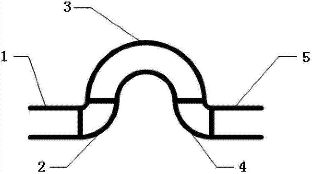
[0053] Such as Figure 1~4 As shown, the present invention provides a multiphase flow adjustment device, comprising:

[0054] At least one basic unit, such as figure 1 , 2 As shown, the basic unit includes:

[0055] The front straight pipe section 1 and the rear straight pipe section 5 are provided with a main elbow 3 protruding upwards between the two, and the main elbow 3 is a 180° elbow,

[0056] The main elbow 3 and the front straight pipe section 1 are connected through the front elbow 2,

[0057] The main bend pipe 3 and the back straight pipe section 5 are connected by a back bend 4,

[0058] Both the front elbow 2 and the rear elbow 4 are 90° elbows.

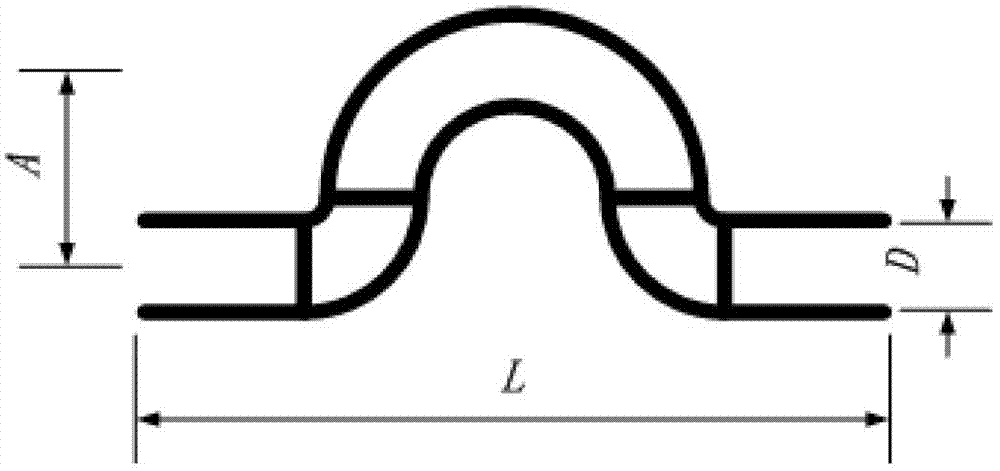
[0059] Such as figure 2 As shown, let the distance between the axis of the straight pipe section and the centerline of the top of the main bend be the amplitude A of the basic unit, the distanc...


PUM


Abstract

The invention relates to a multiphase flow regulation device and a method for restraining slug flow by utilizing same. The multiphase flow regulation device comprises at least one basic unit, each basic unit comprises a front straight tube section and a rear straight tube section, a main bent tube with a bending angle at 180 degrees protrudes upwards and is arranged between the front straight tube section and the rear straight tube section, the main bent tube is connected with the front straight tube section via a front bent head with a bending angle at 90 degrees and connected with the rear straight tube section via a rear bent head with a bending angle at 90 degrees. The multiphase flow regulation device is reasonable in structure, the bending radius of the main bent tube is large, so that a wave-shaped tube is large in 'waving' range, and gas storage at the top of the main bent tube and generation of mixing effect are facilitated. By the aid of the straight tube sections for connecting the basic units, the total length of the multiphase flow regulation device can be adjusted conveniently, and the multiphase flow regulation device can be placed on a plane stably. The method for restraining slug flow by utilizing the multiphase flow regulation device is applicable to severe slug flow and hydraulic power slug flow, and is simple to operate without being allocated with extra hardware and software.

Description

Technical field [0001] The present invention involves the field of stream flow in the sea oil and gas field development system. Specifically, it is a method of multi -phase current flow adjustment device and using its inhibitory segment flow.The segment stream refers to the strong segment plug and hydraulic segmentation flow. Background technique [0002] The maritime oil and gas field development system usually includes 4 subsystems including underwater production system, infusion pipeline-riser system, water fixed / floating structural facilities and upper processing systems. [0003] In the early and at the end of the development of oil and gas fields, when the output of oil and gas is low, the strong stream flow is often generated in the transmission pipeline-riser system.The strong segmentation flow refers to: the length of the liquid plug is at least 1 times the stream of the riser length. It has a periodic period. Each cycle includes 4 stages: liquid pluggingBroken / liquid fa...

Claims


Application Information

Patent Timeline
Patent Type & Authority Applications(China)
IPC IPC(8): E21B17/01E21B43/01
Inventor 邢兰昌耿艳峰
Owner 青岛红嘴鸟科技有限公司
Why Eureka
Try Eureka