Hydraulic filling type central air-conditioning unit

A central air-conditioning, flooded technology, applied in the direction of refrigerators, heating methods, refrigeration components, etc., can solve the problems of unit evaporator freezing, shortening the service life of the unit, and losing the function of the unit

Active Publication Date: 2012-11-07
广东雅士电器有限公司
View PDF5 Cites 9 Cited by
  • Summary
  • Abstract
  • Description
  • Claims
  • Application Information

AI Technical Summary

Problems solved by technology

[0002] The flooded central air-conditioning unit belongs to the vapor compression air-conditioning unit, and usually includes two types: the flooded water-cooled central air-conditioning unit and the flooded ground-source heat pump central air-conditioning unit. High-end features, currently used in buildings, but the application of flooded central air conditioners has the problem of evaporator freezing. The evaporator is a component used for heat exchange. Through the heat exchange between the flowing water and the flowing refrigerant, the heat of the water is transferred to the refrigerant, so that the temperature of the water drops, causing the evaporator to freeze, especially when the flooded ground source heat pump central air conditioning unit is heated in winter Under working conditions, the temperature of the working environment is low, and the refrigerant in the evaporator absorbs the heat of the water in the evaporator when it vaporizes, making the evaporator easier to freeze. service life, if it is heavy, it will cause the unit to lose i

Method used


Image

  • Hydraulic filling type central air-conditioning unit
  • Hydraulic filling type central air-conditioning unit

Examples


Embodiment 1

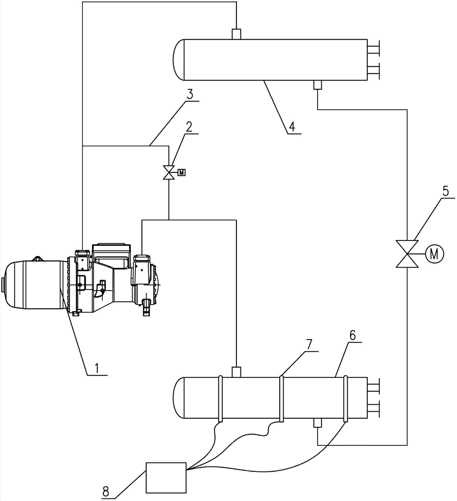
[0019] Such as figure 1 As shown, a flooded central air-conditioning unit includes a compressor 1, a condenser 4, an expansion valve 5, an evaporator 6 and a control unit for controlling the operation of the unit, and the outlet of the compressor 1 is connected to the outlet of the condenser 4 Refrigerant inlet, the refrigerant outlet of the condenser 4 is connected to the inlet of the expansion valve 5, the outlet of the expansion valve 5 is connected to the refrigerant inlet of the evaporator 6, and the refrigerant outlet of the evaporator 6 is connected to The inlet of the compressor 1 also includes a bypass pipeline 3 that passes the high-pressure refrigerant in the condenser 4 into the evaporator 6, and one end of the bypass pipeline 3 is connected to the outlet of the compressor 1 and On the pipe between the refrigerant inlet of the condenser 4, the other end is connected to the pipe between the inlet of the compressor 1 and the refrigerant outlet of the evaporator 6, an...

Embodiment 2

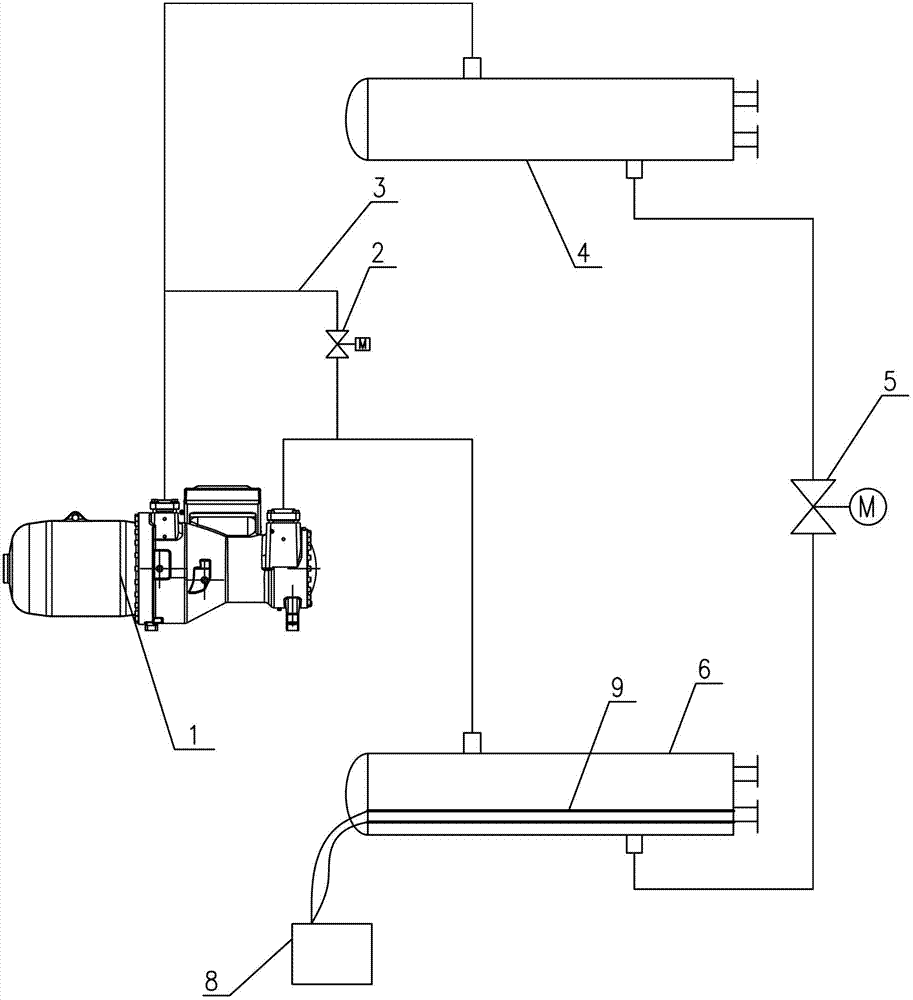
[0024] Such as figure 2 As shown, the difference between embodiment two and embodiment one is that the strip electric heater 9 installed in the evaporator 6 is used instead of the annular electric heater, and the strip electric heater 9 is directly connected to the evaporator 6 The water inside is heated by contact.


PUM


Abstract

The invention discloses a hydraulic filling type central air-conditioning unit and belongs to the technical field of central air-conditioning. The hydraulic filling type central air-conditioning unit comprises a compressor, a condenser, an expansion valve, an evaporator and a control unit for controlling a machine unit to run and further comprises a bypass pipe enabling a high-pressure refrigerant in the condenser to be led into the evaporator. The bypass pipe is provided with a solenoid valve controlling on-off of the bypass pipe, the evaporator is provided with a temperature sensor for detecting outflow water temperature, and the temperature sensor and the solenoid valve are electrically connected with the control unit. When the temperature of outflow water of the evaporator is larger than a set value, the compressor and the expansion valve are turned off, the high-pressure refrigerant is led into the evaporator by opening the bypass pipe, evaporating temperature of the refrigerant is improved, the speed of lowering the water temperature is slowed down, water in the evaporator is kept flowing continuously, the compressor and the expansion valve are restarted until the water in the evaporator reaches a certain temperature, and accordingly freezing of the evaporator is avoided.

Description

technical field [0001] The invention relates to the technical field of central air-conditioning units, in particular to a flooded central air-conditioning unit. Background technique [0002] The flooded central air-conditioning unit belongs to the vapor compression air-conditioning unit, and usually includes two types: the flooded water-cooled central air-conditioning unit and the flooded ground-source heat pump central air-conditioning unit. High-end features, currently used in buildings, but the application of flooded central air conditioners has the problem of evaporator freezing. The evaporator is a component used for heat exchange. Through the heat exchange between the flowing water and the flowing refrigerant, the heat of the water is transferred to the refrigerant, so that the temperature of the water drops, causing the evaporator to freeze, especially when the flooded ground source heat pump central air conditioning unit is heated in winter Under working conditions,...

Claims


Application Information

Patent Timeline
IPC IPC(8): F24F11/02F25B41/06
CPCY02B30/72Y02B30/70
Inventor 吴松曹银生
Owner 广东雅士电器有限公司
Why Eureka
Try Eureka