Corrugated pipe condensation heat exchanger and manufacture method thereof

A technology of condensing heat exchanger and manufacturing method, which is applied in the direction of air heater, fluid heater, energy-saving heating/cooling, etc. It can solve the problems of large smoke exhaust resistance, difficult to fix the shape, and insufficient heat exchange of pipelines, etc., to achieve Improved heat transfer efficiency, simple manufacturing process, and consistent tube spacing

Inactive Publication Date: 2012-11-07
MACRO THERMAL ENERGY TECH
View PDF8 Cites 4 Cited by
  • Summary
  • Abstract
  • Description
  • Claims
  • Application Information

AI Technical Summary

Problems solved by technology

However, one problem is that due to the large resilience of the stainless steel bellows itself, the shape is difficult to fix, which makes the product stability of the condensing heat exchanger poor during mass production, and some products have large smoke exhaust resistance and insufficient gas combustion. ; And then lead to high CO (carbon monoxide) content in the exhausted flue gas, flue gas instability; seriously affect the quality of products in mass production
In addition, due to the uneven spacing between the tubes of the bellows condensing heat exchanger, some pipelines do not have sufficient heat exchange, which not only causes waste of materials, but also has low heat exchange efficiency

Method used


Image

  • Corrugated pipe condensation heat exchanger and manufacture method thereof
  • Corrugated pipe condensation heat exchanger and manufacture method thereof
  • Corrugated pipe condensation heat exchanger and manufacture method thereof

Examples


Embodiment Construction

[0033] In order to further illustrate the essence of the present invention, the specific implementation of a bellows condensing heat exchanger provided by the present invention will be described in detail below with reference to the accompanying drawings.

[0034] Examples of condensing heat exchangers

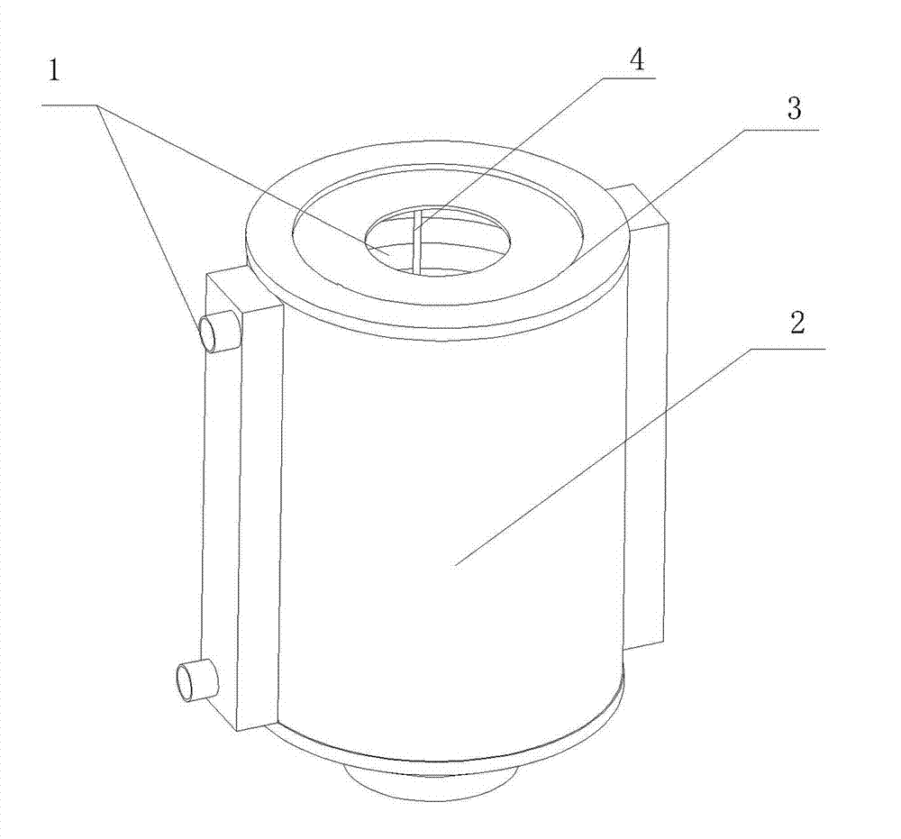
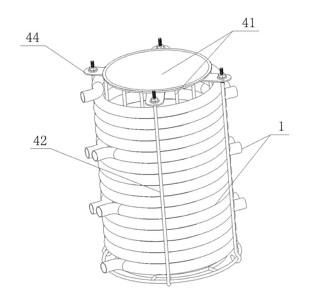
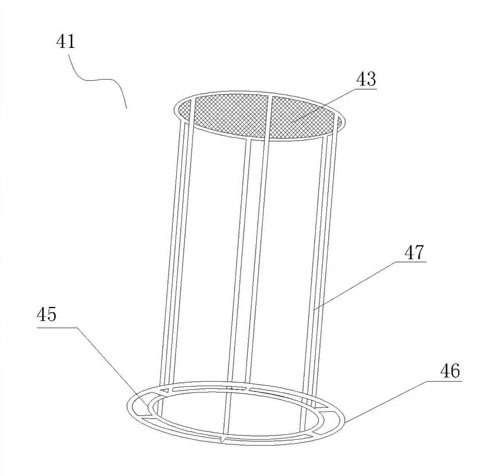
[0035] Such as figure 1 , figure 2 As shown, a bellows condensing heat exchanger includes: a bellows 1, a condensing heat exchanger shell 2 and an upper and lower end cover 3, and it is characterized in that a frame 4 is arranged inside the condensing heat exchanger shell 2, At least one group of bellows 1 is coiled and fixed on the frame 4 to form a helical structure, the pitch of the helical structure is equal, and the helical axes are the same straight line. Preferably, the bellows 1 is made of stainless steel and consists of six groups coiled continuously on the frame; the frame 4 includes: a frame body 41, a fixed rod 42 and a pressing piece 44 movably mounted on the...


PUM


Abstract

The invention provides a corrugated pipe condensation heat exchanger. The corrugated pipe condensation heat exchanger comprises corrugated pipes, a condensation heat exchanger casing, an upper end cover and a lower end cover, wherein a frame is arranged in the condensation heat exchanger casing, the corrugated pipes are coiled and fixed on the frame to form a spiral structure, the thread pitch of the spiral structure is identical, and spiral axes are the same straight line. The invention further provides a manufacture method of the corrugated pipe condensation heat exchanger. The manufacture method comprises the steps of frame manufacture, installation of the corrugated pipe and installation of the condensation heat exchanger casing. The step of the installation of the corrugated pipe is that the stainless steel corrugated pipes are first and sequentially coiled on a connecting rod of a frame main body for form a coaxial structure by means of a bamboo basket weaving mode and then are fixed on the connecting rod through fixing rods by means of an extruding mode to form the identical-thread-pitch structure. Compared with a traditional condensation heat exchanger, the corrugated pipe condensation heat exchanger has the advantages of being identical in size during batch production, further enables inner combustion to be full and achieves energy saving and environmental protection.

Description

technical field [0001] The invention relates to the field of fluid heaters utilizing latent heat in flue gas, in particular to a bellows condensation heat exchanger and a manufacturing method thereof. Background technique [0002] The condensing heat exchanger further cools the exhausted flue gas, condenses the water vapor in the flue gas and releases latent heat to improve the heat utilization rate, and is very commonly used in high-efficiency and energy-saving home appliances. In particular, on the basis of the traditional shell and tube heat exchanger, the bellows heat exchanger applies the enhanced heat transfer theory and the unique design of the peak and trough of the heat exchange tube, which not only inherits the firmness and durability of the shell and tube heat exchanger. , safety, reliability and other advantages, while overcoming the disadvantages of poor heat transfer capacity and easy scaling, it has been widely used in gas water heaters and gas wall-hung boile...

Claims


Application Information

Patent Timeline
Patent Type & Authority Applications(China)
IPC IPC(8): F24H8/00B23P15/26
CPCY02B30/102Y02B30/00
Inventor 余少言仇明贵陈耀华
Owner MACRO THERMAL ENERGY TECH
Why Eureka
Try Eureka