

Full-size quick blade detection method and equipment
A full-scale, blade-based technology, applied to measuring devices, instruments, optical devices, etc., can solve problems such as inability to obtain information, large human errors, and long measurement time, so as to achieve accurate data, improve accuracy and efficiency, and avoid adverse effects Effect
- Summary
- Abstract
- Description
- Claims
- Application Information
AI Technical Summary
Problems solved by technology
Method used
Image

Examples
Embodiment Construction
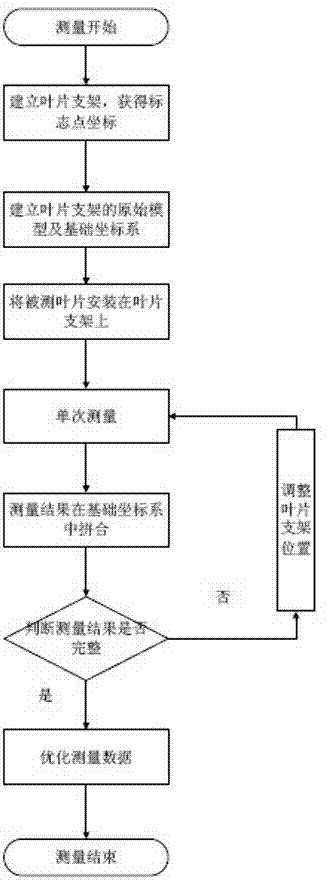
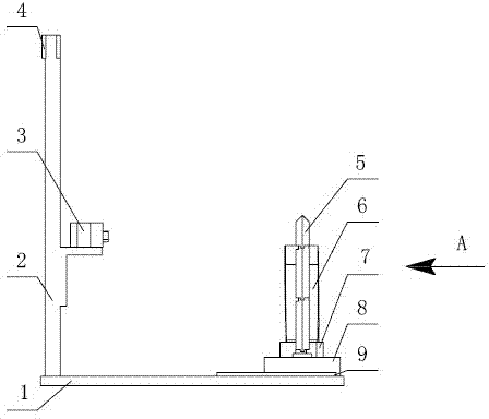
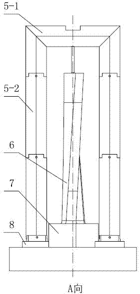
[0021] as attached figure 1 As shown, a method for rapid full-scale detection of blades in this embodiment is based on a three-dimensional optical measurement system and surface structured light projection profilometry to detect blades, and the optical three-dimensional scanning measurement head projects a sinusoidal stripe surface structure to the surface of the measured blade Light, use the heterodyne multi-frequency phase shift method to solve and expand the phase, take the phase as the constraint condition of image matching, use the limit constraint relationship in binocular stereo vision to obtain the three-dimensional point cloud data of the blade surface, and realize the optical measurement of the blade surface , due to the complex shape of the blade, it is difficult to obtain complete data in a single measurement, so multiple measurements are required to obtain the measurement results of the entire blade by splicing. The detection method comprises the following steps: ...
PUM
 Abstract
Description
Claims
Application Information