Electro-hydraulic flat-pushing clamping device

A technology of clamping device and driving device, which is applied in the field of fixtures and can solve problems such as poor synchronization performance of clamping blocks and uncontrollable clamping force.

Inactive Publication Date: 2012-11-07
CHANGCHUN NEW TESTING MACHINE
View PDF7 Cites 4 Cited by
  • Summary
  • Abstract
  • Description
  • Claims
  • Application Information

AI Technical Summary

Problems solved by technology

[0005] The purpose of the present invention is to propose an electro-hydraulic horizontal push clamping device to solve the problems of poor synchronization performance of two clamping blocks and uncontrollable clamping force in the clamping process of the two-way horizontal push clamping device in the prior art

Method used


Image

  • Electro-hydraulic flat-pushing clamping device
  • Electro-hydraulic flat-pushing clamping device
  • Electro-hydraulic flat-pushing clamping device

Examples


Embodiment 1

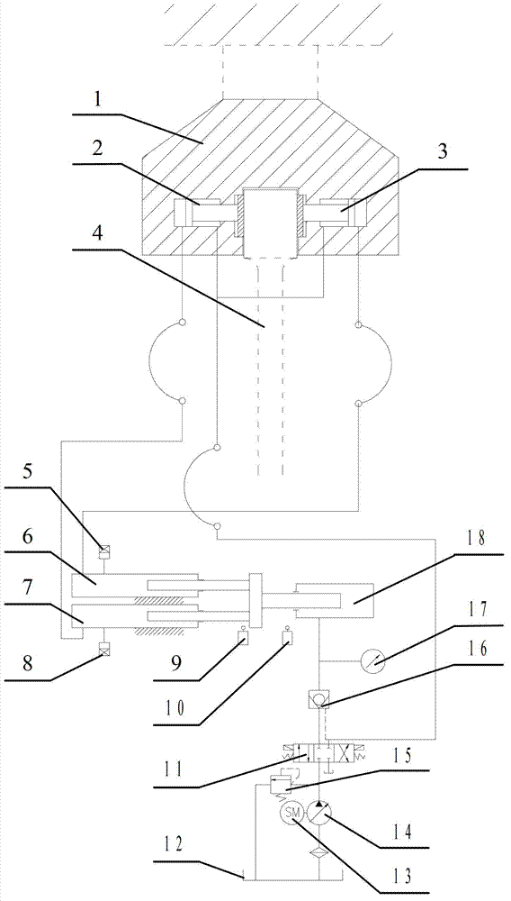
[0038] See attached figure 1 and attached Figure 5 , 6 , the flat push type clamping device of the present invention comprises collet body 1, piston cylinder A2, piston cylinder B3, plunger cylinder A7, plunger cylinder B6 and drive device composition; Described collet body 1 comprises body 101, rear end Cover A102, piston A103, front end cover A104, transition plate A105, snap ring A106, clamp block A107, clamp block B108, snap ring B109, transition plate B110, front end cover B111, piston B112, rear end cover B113; The block A107 is connected to the piston A103 through the transition plate A105; the front end cover A104 is close to the clamp block A107, and the rear end cover A102 is located at the outer end of the body 101; the clamp block B108 is connected to the piston B112 through the transition plate B110; the front end cover B111 is close to the clamp Block B108, the rear end cover B113 is located at the outer end of the body 101; the piston rod of the piston cylind...

Embodiment 2

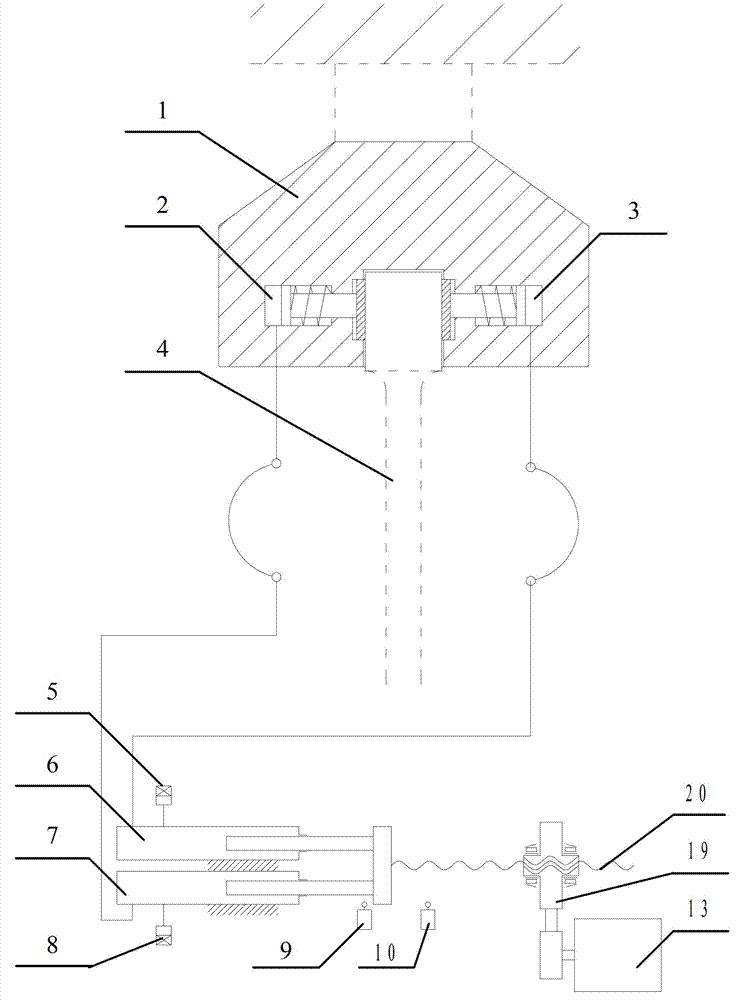
[0043] See attached figure 2 The difference between this embodiment and Embodiment 1 is that the driving device includes a servo motor 13, a reducer 19, and a ball screw 20, and the ball screw 20 is connected to the plunger cylinder A7 and the column of the plunger cylinder B6. The plug cylinder is connected, and the servo motor 13 drives the ball screw 20 to rotate through the reducer 19; the loosening system is that a spring is installed in the rod cavity of the piston cylinder A2 and the piston cylinder B3, and the clamping block is moved away from the test by the restoring force of the spring. Move in the direction of sample 4.

Embodiment 3

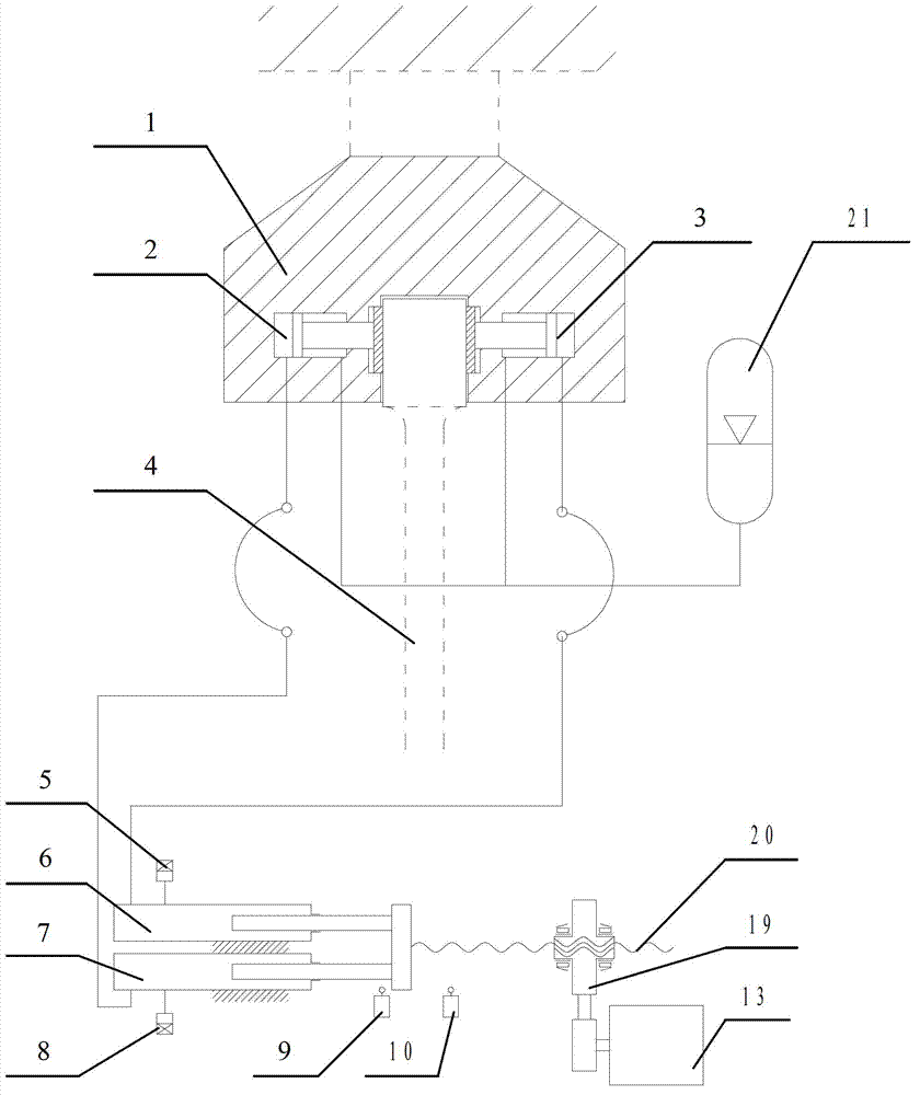
[0045] See attached image 3The difference between this embodiment and Embodiment 1 is that the driving device includes a servo motor 13, a reducer 19, and a ball screw 20, and the ball screw 20 is connected to the plunger cylinder A7 and the column of the plunger cylinder B6. The plug cylinder is connected, and the servo motor 13 drives the ball screw 20 to rotate through the reducer 19; the loosening system is that the piston cylinder A2 and the piston cylinder B3 have an accumulator 21 connected to the rod chamber, and when the sample 4 is loosened, through The accumulator 21 makes the pistons of the piston cylinder A2 and the piston cylinder B3 move away from the clamp block.


PUM


Abstract

The invention discloses an electro-hydraulic flat-pushing clamping device, and belongs to the technical field of fixtures. The electro-hydraulic flat-pushing clamping device solves problems of poor synchronization performance and uncontrollability in clamping force when an existing bidirectional flat-pushing clamping device is used for clamping. The electro-hydraulic flat-pushing clamping device comprises a chuck, a piston cylinder A, a piston cylinder B, a plunger type cylinder A, a plunger type cylinder B and a driving device, a piston rod of the piston cylinder A and a piston rod of the piston cylinder B are respectively fixedly connected with clamp splices in the chuck, the piston cylinder A, the piston cylinder B, the plunger type cylinder A and the plunger cylinder B form a communicating vessel, an extending end of a plunger rod of the plunger type cylinder A is fixedly connected with an extending end of a plunger rod of the plunger type cylinder B, and the plunger rod of the plunger type cylinder A and the plunger rod of the plunger type cylinder B are driven by the driving device to move. As the piston cylinder A, the piston cylinder B, the plunger type piston A and the plunger type cylinder B form the communicating vessel, the clamping synchronization performance of the clamp splices is good, and clamping force can be adjusted by controlling rotation of the motor to adjust pressure.

Description

technical field [0001] The invention belongs to the technical field of jigs, and in particular relates to an electro-hydraulic dynamic horizontal push type clamping device used in the tensile test of a material testing machine. Background technique [0002] Determining the mechanical properties of materials by testing is very important in scientific research and industrial and agricultural production, and it is widely used. In the tensile test of materials, the firmness of the clamping of the sample is very important for the accurate determination of the mechanical properties of the material and the acquisition of credible and reliable test data. In the commonly used wedge clamping method, slippage usually occurs, which is not conducive to the test, so the non-slip horizontal push clamping method has been recognized and adopted by the industry. [0003] The so-called flat push clamping is to apply a force perpendicular to the direction of the tensile force line to the clamp...

Claims


Application Information

Patent Timeline
Patent Type & Authority Applications(China)
IPC IPC(8): G01N3/04
Inventor 张学成霍宏艳姜立波
Owner CHANGCHUN NEW TESTING MACHINE
Why Eureka
Try Eureka