
Vehicle detector circuit

A vehicle detector and circuit technology, applied in the field of vehicle detectors, can solve problems such as poor stability, large frequency drift, and slow start-up, and achieve the effects of high frequency stability, high reliability, and fast start-up.

Inactive Publication Date: 2012-11-07
上海澳星光电科技有限公司
View PDF6 Cites 0 Cited by
  • Summary
  • Abstract
  • Description
  • Claims
  • Application Information

AI Technical Summary

Problems solved by technology

Such circuit design defects: the circuit structure is simple, it is a basic LC oscillator circuit, and the stability is poor; the frequency drift is large; the inductance range of the external coil is limited; the oscillation is slow; there is no feedback input, and the stability of the oscillation frequency cannot be guaranteed

Method used


Image

  • Vehicle detector circuit
  • Vehicle detector circuit
  • Vehicle detector circuit

Examples


Embodiment Construction

[0019] In order to make the technical means, creative features, goals and effects achieved by the present invention easy to understand, the present invention will be further described below in conjunction with specific illustrations.

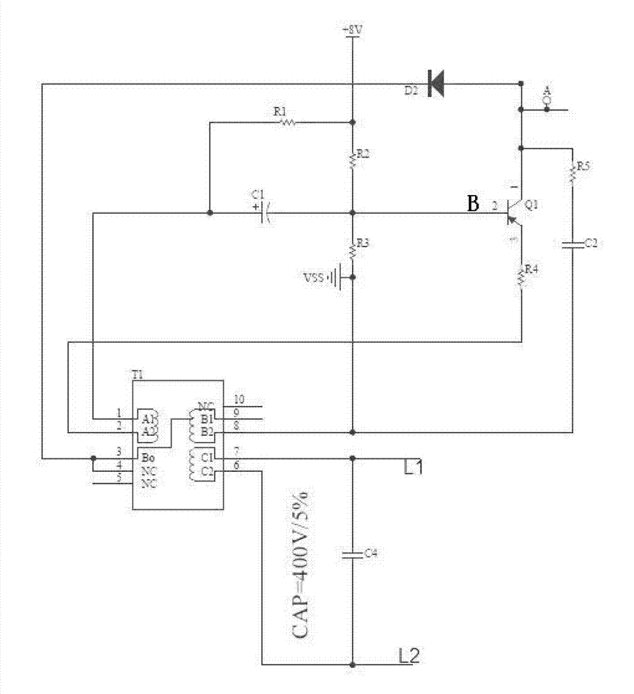
[0020] refer to figure 2 , a vehicle detector circuit, including a transformer T1, the second primary winding C1-C2 of the transformer T1 is connected with a second frequency selection circuit, and the second frequency selection circuit includes a parallel inductor (L1, L2), and the electrolytic capacitor C4 connected to the parallel inductance is formed to perform preliminary frequency selection. The positive feedback circuit includes the secondary winding A1A2 coil of the transformer T1 and the polar capacitor C1, and the first primary winding B0 of the transformer T1- B2 coil is the first frequency selection circuit, the first frequency selection circuit is composed of the fifth resistor R5, the second capacitor C2 and the first primary wind...


PUM


Abstract

The invention discloses a vehicle detector circuit, which comprises frequency selection circuits and a positive feedback circuit, wherein a first frequency selection circuit consists of a fifth resistor, a second capacitor and a first primary winding coil of a transformer and is used for the frequency selection of an electrified pulse; a second frequency selection circuit comprises a parallel inductor connected with an external coil and an electrolytic capacitor connected with the parallel inductor and is used for primary frequency selection; the positive feedback circuit comprises a secondary winding coil of the transformer, and is coupled by the first primary winding coil of the transformer and then is fed back to the base of a triode through a polar capacitor; the collector of the triode is connected with the first frequency selection circuit; and a second primary winding of the transformer is connected with the second frequency selection circuit. Due to the frequency selection circuits and the positive feedback circuit, the vehicle detector circuit is high in reliability, fast in oscillation starting, high in frequency stability and low in drift.

Description

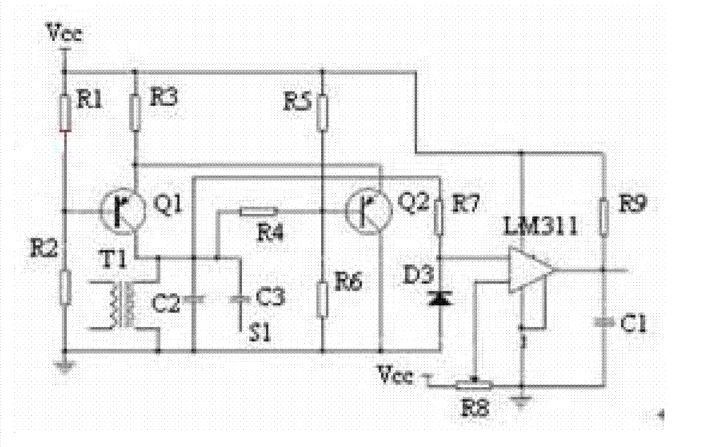
technical field [0001] The invention relates to the field of vehicle detectors, in particular to a vehicle detector circuit. Background technique [0002] The vehicle coil detection circuit currently used mainly includes a two-stage amplifier and a power amplifier to amplify the signal, refer to figure 1 As mentioned above, the base bias of the triode Q1 is set by the first resistor R1 and the first R2 resistor, and then a simple LC oscillation is formed by the primary coil of the transformer T1 and the capacitor C2, which is input to the operational amplifier through the third R7 and then output . Such circuit design defects: the circuit structure is simple, it is a basic LC oscillation circuit, and the stability is poor; the frequency drift is large; the inductance range of the external coil is limited; the oscillation is slow; there is no feedback input, and the stability of the oscillation frequency cannot be guaranteed. Contents of the invention [0003] The technic...

Claims


Application Information

Patent Timeline
Patent Type & Authority Applications(China)
IPC IPC(8): G01V3/11
Inventor 马志军何文辉陈克俭陈霞胡晓月
Owner 上海澳星光电科技有限公司
Learn More