
Automatic LED (light-emitting diode) display screen correction method

A technology of LED display screen and calibration method, applied in static indicators, signal transmission systems, instruments, etc., can solve the problems of inability to complete calibration work, waste of human resources, complicated calibration process, etc., to save manpower, improve accuracy, Reduce the effect of the information exchange process

Active Publication Date: 2012-11-07
XIAN NOVASTAR TECH
View PDF9 Cites 24 Cited by
  • Summary
  • Abstract
  • Description
  • Claims
  • Application Information

AI Technical Summary

Problems solved by technology

The traditional calibration process is very complicated, requiring a lot of operations between each link, and if one of the steps is misoperated, the calibration work will not be completed
Therefore, the traditional correction method has too many operating links, high error rate, and requires long-term information exchange between different personnel, which may cause misunderstanding and misjudgment, and requires a lot of repeated communication, resulting in waste of human resources and poor correction efficiency. lower

Method used


Image

  • Automatic LED (light-emitting diode) display screen correction method
  • Automatic LED (light-emitting diode) display screen correction method

Examples


Embodiment Construction

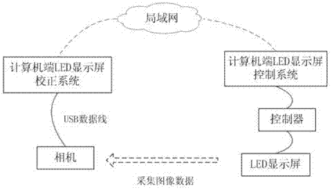
[0030] Such as figure 1 As shown, the system structure of the LED of the present invention is mainly composed of a computer-side LED display correction system (A-side) and a computer-side LED display control system (B-side) for establishing a network connection (taking a wireless local area network as an example). The LED display screen is equipped with an image acquisition device (SLR camera is preferred), the lens points to the LED display screen, the lens covers the full LED screen, and can be aimed at a certain partition of the LED display screen as required. The image acquisition equipment can collect the image information of the LED display with high quality, and transmit it to the correction system through the USB data cable. The correction coefficient calculation module in the correction system sends the calculated correction coefficient to the control system of the LED display through the network connection. Thereby adjusting the configuration parameters of the LED di...


PUM


Abstract

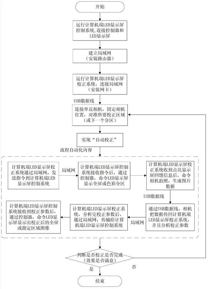
The invention provides an automatic LED (light-emitting diode) display screen correction method. The automatic correction method comprises the following steps: (1) network connection is established; (2) an A end sends a display instruction to a B end, the B end controls the full-screen or the specific sub-area of the LED display screen to display the image; (3) the A end controls image acquisition equipment to aim at a to-be-corrected area of the LED display screen, acquires the image data and uploads the image data to the A end for analysis and process to generate correction coefficients, a controller of the B end sends the correction coefficients to a receiving card of the LED display screen, so that the LED display screen displays the corrected full-screen or specific-area image; and (5) the image acquisition equipment acquires the image in the to-be-corrected area again, the A end analyzes point-to-point brightness, judges whether the correction effect is satisfied. By using the correction method, the correction accuracy is increased, the labor intensity is saved, and the correction time is shortened effectively.

Description

technical field [0001] The invention relates to the field of point-by-point correction of LED display screens, in particular to a method for correcting LED display screens. Background technique [0002] The point-by-point correction function of the LED display plays an important role in the later maintenance of the LED display, which can significantly improve the brightness and chromaticity uniformity of the display. In the calibration process of the LED display, because there are many links involved, a lot of information interaction and cooperative operations are required. The entire process will require at least 2 or more staff to complete the calibration work. [0003] In general, calibration can be divided into 3 steps: [0004] Use the image acquisition device to measure the designated area of ​​the LED display. In this link, an engineer needs to operate in the control room, connect the controller through the computer-side control software, and let the LED display dis...

Claims


Application Information

Patent Timeline
Patent Type & Authority Applications(China)
IPC IPC(8): G09G3/00G09G3/32G08C17/02
Inventor 宗靖国袁胜春
Owner XIAN NOVASTAR TECH
Learn More