Method for measuring distance and measuring device for it

a technology of measuring device and distance, applied in the field of methods, can solve the problems of interference, so-called cross feed, and increased reaction time disadvantage, and achieve the effect of reducing the reaction time of the measuring system

Active Publication Date: 2007-02-13
ROBERT BOSCH GMBH
View PDF13 Cites 19 Cited by
  • Summary
  • Abstract
  • Description
  • Claims
  • Application Information

AI Technical Summary

Benefits of technology

[0020]Because of the mutually time-offset emission of measuring pulses of the distance sensors of an emission group, an artificial running time difference between the first measurement and the verification measurement (or repeat measurement) is superposed on the cross feed echos within the emission group. Because of this running time difference of the measuring pulse echos between the two measurements, the cross feed echos may then be filtered out. This provides the additional advantage that the measuring range is able to be increased, since a misinterpretation of the measuring receiving signal is prevented. In the case of emission offset in time, those running times of the directly reflected measuring pulse echos and of the direct cross echos which originate from the distance sensors directly adjacent to the receiving distance sensor are maintained. The running times of the cross-reflecting, cross-feeding measuring impulses (cross feed echos), which originate from distance sensors other than the receiving distance sensor or the distance sensor directly adjacent to the receiving distance sensor, are different and are able to be filtered out. Therefore, it is no longer necessary that two different, simultaneously emitting sensors of a given emitting group are separated by at least three sensors of different emitting group sensors. This provides the advantage that, at the front end and the rear end of a motor vehicle, respectively, for example, one emitting group may be saved, and the reaction time of the distance measuring system may be improved.
[0022]The offset in time may amount to only a fraction of the time which a distance sensor requires to make a distance measurement. The reaction time of the system is consequently not impaired by the offset in time, thereby allowing the distance sensors to carry out their measurements substantially faster than the existing measuring systems.

Problems solved by technology

In the case of the four to six distance sensors usually used per vehicle side, e.g., in the case of six distance sensors in the front region of the vehicle, the reaction time is increased disadvantageously by the sequential distance measurement of the individual distance sensors, i.e., the measurements are staggered in time.
In the case of greater measuring ranges, there is additionally the danger that interference, so-called cross feed, may appear within the emitting groups which are arranged for short measuring ranges.
Therefore, it is necessary in conventional approaches to limit the measuring range or to emit the measuring pulses sequentially by the distance sensor, which has a negative influence on the reaction time of the measuring system.
This disadvantageously results in a relatively great reaction time.
However, the limitation of measuring range R has the disadvantage that obstacles are detected too late under certain circumstances.

Method used


Image

  • Method for measuring distance and measuring device for it
  • Method for measuring distance and measuring device for it
  • Method for measuring distance and measuring device for it

Examples


Embodiment Construction

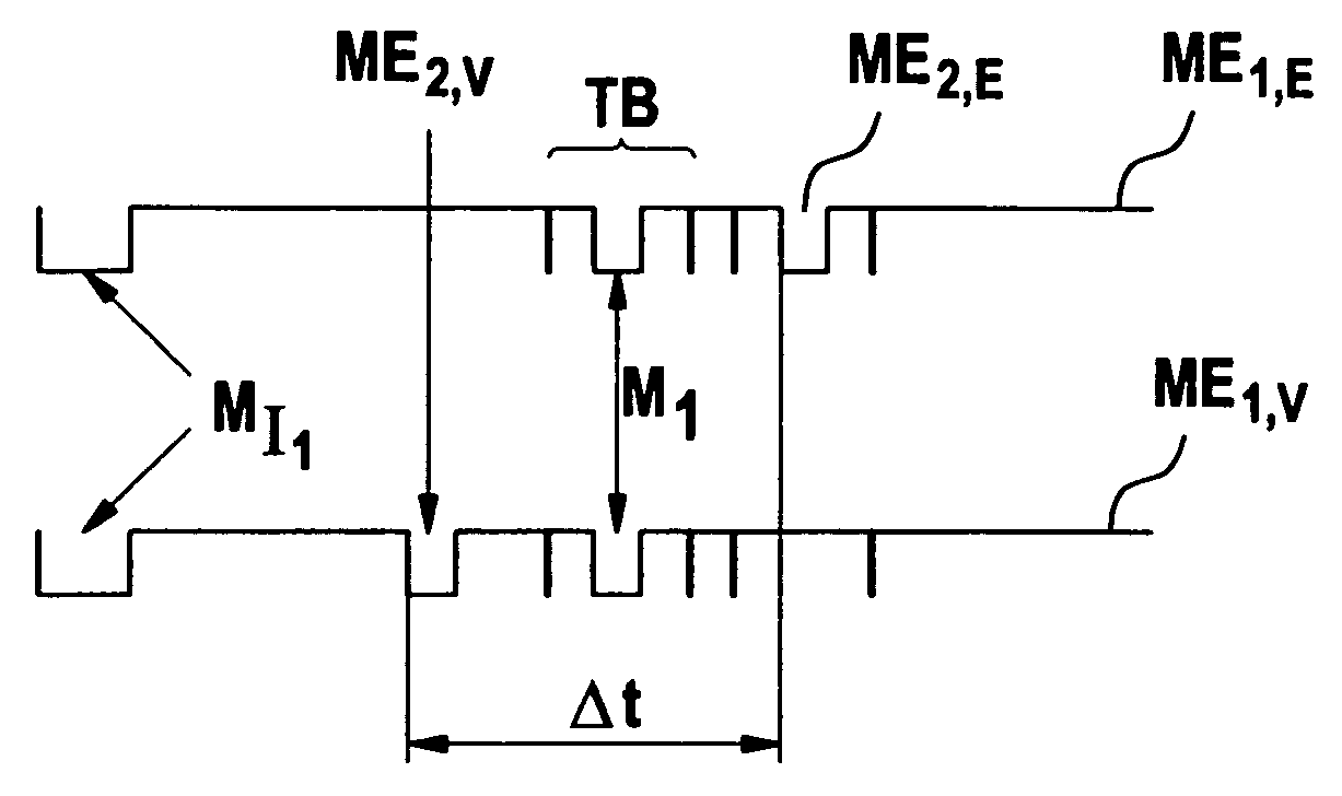
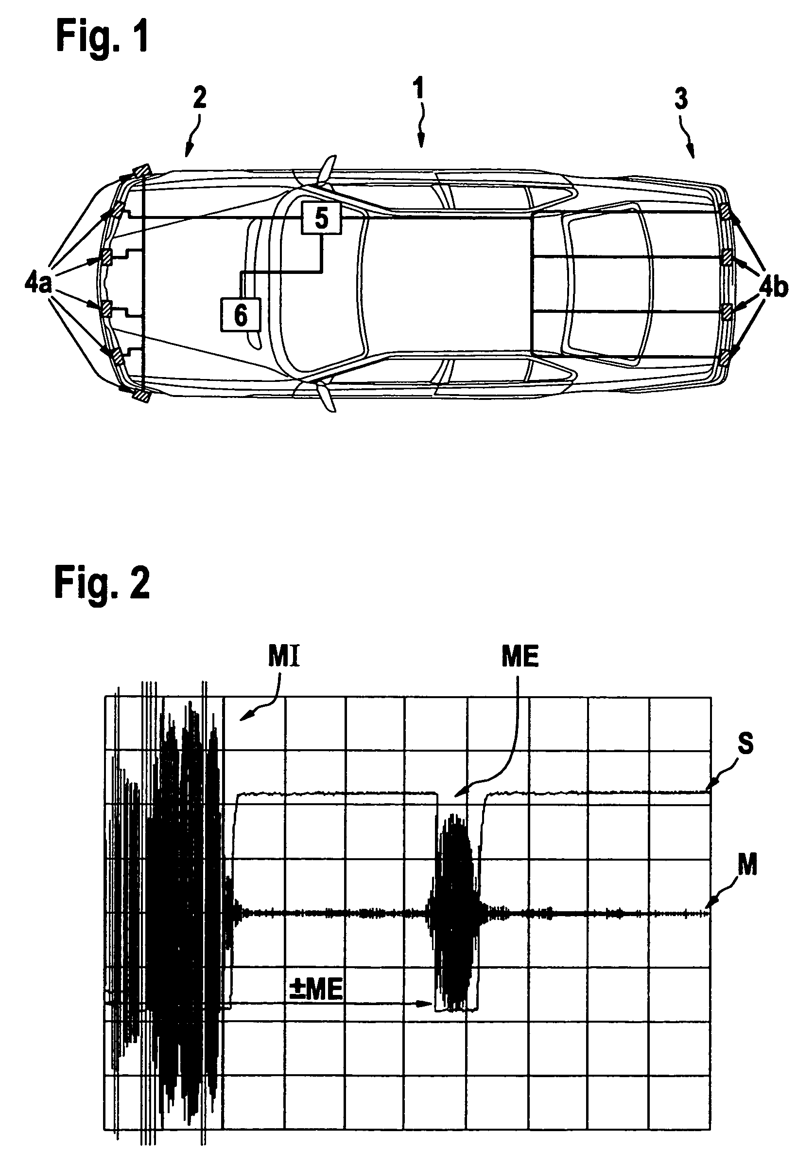
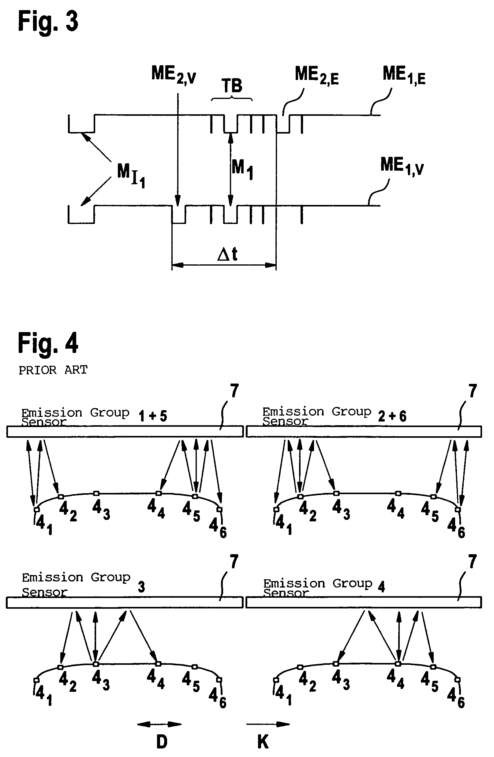
[0039]In FIG. 1, a top view of a motor vehicle 1 is shown. At the front end 2 and at the rear end 3, a plurality of distance (e.g., ultrasound sensors) sensors 4 (4a designating the sensors in the front, and 4b designating the sensors in the rear) are built into the bumper, each of which sensors has an emitter for emitting measuring pulses MI and a receptor for receiving measuring pulse echos ME. Distance sensors 4a and 4b are connected to a control and evaluation unit 5, which, on its part, may be connected to a central vehicle control unit 6 via a bus system, such as a CAN bus. Control and evaluation unit 5 is used for activating distance sensors 4a and 4b, and for evaluating the received measuring signals for determining the distance from possible obstacles, and for transmitting the distance information to an optical or acoustical indicator system, e.g., via the CAN bus and the central control unit 6.

[0040]In FIG. 2, an example chart of a measuring signal M (having components MI ...


PUM


Abstract

A method for distance measuring using at least two contact-less distance sensors, e.g., ultrasound sensors, is provided, which distance sensors each have one emitter for emitting measuring pulses (MI) and one receptor for receiving measuring pulse echos (ME). The distance from an obstacle that reflects the measuring pulse (MI) is determined from the time difference between the measuring pulse (MI) and the received measuring pulse echo (ME). A first measurement is performed, which involves alternatingly emitting by the at least two distance sensors the measuring pulses (MI) offset in time by a first offset, and subsequently receiving the measuring pulse echos (ME) by the distance sensors. In addition, a verification measurement is performed, which involves alternatingly emitting by the at least two distance sensors the measuring pulses (MI) offset in time by a second offset, which is different from the first offset in time used in the first measurement.

Description

FIELD OF THE INVENTION[0001]The present invention relates to a method for measuring a distance using at least two distance sensors that are not in contact.BACKGROUND INFORMATION[0002]In a method for measuring distances using ultrasound sensors, which respectively have an emitter for transmitting measuring pulses and a receptor for receiving measuring pulse echos, the distance from an obstacle that reflects the measuring pulse is determined from the time difference between the measuring pulse and the reflected measuring pulse echo. This method may be implemented using a measuring device including: a) at least two ultrasound sensors which each have an emitter for transmitting measuring pulses and a receptor for receiving measuring pulse echos; b) a control unit; and c) an evaluation unit connected to the distance sensors.[0003]The corresponding measurements of distance may be used for parking-assistance functions in motor vehicles, e.g., in order to detect obstacles in the surrounding...

Claims


Application Information

Patent Timeline
Patent Type & Authority Patents(United States)
IPC IPC(8): B60Q1/00G01S15/931G01S7/527G01S15/87
CPCG01S7/527G01S15/876G01S15/931G01S15/878G01S2013/9389G01S2013/9314G01S15/003G01S2013/93275
Inventor HERDER, BJOERN
Owner ROBERT BOSCH GMBH
Why Eureka
Try Eureka