Wafer drying device

A wafer drying and wafer technology, applied in drying gas arrangement, drying, dryer and other directions, can solve the problems of accelerated mechanical equipment loss, impact on the overall stability of the wafer, damage to the wafer, etc., to achieve low manufacturing costs , The manufacturing difficulty is small, and the effect of reducing the machining accuracy

Active Publication Date: 2012-11-07
TSINGHUA UNIV
View PDF9 Cites 21 Cited by
  • Summary
  • Abstract
  • Description
  • Claims
  • Application Information

AI Technical Summary

Problems solved by technology

However, the wafer needs to be rotated at a high speed, and the drying process will be added at the same time, which will affect the overall stability of the wafer, and even damage the wafer in severe cases.
At the same time, the high-speed rotation of the rotary table will also accelerate the loss of mechanical equipment

Method used


Image

  • Wafer drying device
  • Wafer drying device
  • Wafer drying device

Examples


Embodiment Construction

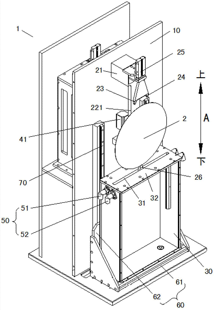
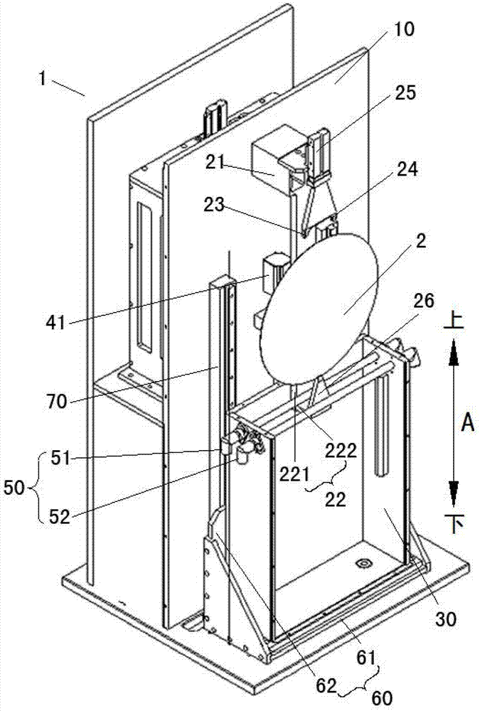
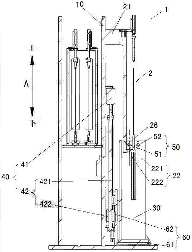
[0022] Embodiments of the present invention are described in detail below, examples of which are shown in the drawings, wherein the same or similar reference numerals designate the same or similar elements or elements having the same or similar functions throughout. The embodiments described below by referring to the figures are exemplary and are intended to explain the present invention and should not be construed as limiting the present invention.

[0023] In describing the present invention, it should be understood that the terms "center", "longitudinal", "transverse", "length", "width", "thickness", "upper", "lower", "front", " Orientation or position indicated by "back", "left", "right", "vertical", "horizontal", "top", "bottom", "inner", "outer", "clockwise", "counterclockwise", etc. The relationship is based on the orientation or positional relationship shown in the drawings, and is only for the convenience of describing the present invention and simplifying the descrip...


PUM


Abstract

The invention discloses a wafer drying device. The wafer drying device comprises a body, a wafer clamping mechanism, a water tank, a water tank driving piece and an isopropyl alcohol (IPA) drying system, wherein the wafer clamping mechanism is arranged on the body and used for supporting a wafer which is directed along a vertical direction; the water tank is arranged on the body moveably up and down, and a rabbet which penetrates the top wall of the water tank along the vertical direction and where the wafer passes through is arranged in the top wall; the water tank driving piece is arranged on the body and connected with the water tank for driving the water tank to move up and down; and the IPA drying system is arranged on the water tank and used for drying the wafer. According to the embodiment of the invention, the wafer drying device has the advantages of small manufacturing difficulty, low manufacturing cost, high reliability and the like, and repositioning precision requirements on a mechanical arm which carries the wafer are greatly reduced.

Description

technical field [0001] The invention relates to the field of semiconductor manufacturing, in particular to a wafer drying device. Background technique [0002] The existing wafer drying device adopts the technology of spinning and drying. However, the wafer needs to be rotated at a high speed, and a drying process will be added at the same time, which will affect the overall stability of the wafer, and even damage the wafer in severe cases. At the same time, the high-speed rotation of the turntable will also accelerate the loss of mechanical equipment. Contents of the invention [0003] The present invention aims at solving one of the above technical problems at least to a certain extent or at least providing a useful commercial choice. Therefore, an object of the present invention is to provide a wafer drying device that can greatly reduce the requirement on repeat positioning accuracy of a manipulator used to transfer wafers. [0004] In order to achieve the above obj...

Claims


Application Information

Patent Timeline
Patent Type & Authority Applications(China)
IPC IPC(8): H01L21/67H01L21/683F26B21/00
Inventor 路新春徐海滨沈攀何永勇
Owner TSINGHUA UNIV
Why Eureka
Try Eureka