Mixed permanent magnet synchronous motor rotor

A permanent magnet synchronous motor technology, applied in the direction of magnetic circuit rotating parts, magnetic circuit shape/style/structure, etc., can solve the problems of high motor cost, low mechanical strength, large magnetic flux leakage coefficient, etc.

Inactive Publication Date: 2012-11-07
岳群生
View PDF8 Cites 7 Cited by
  • Summary
  • Abstract
  • Description
  • Claims
  • Application Information

AI Technical Summary

Problems solved by technology

[0004] The present invention provides a hybrid permanent magnet synchronous motor rotor in order to solve the problems of low mechanical strength of the existing permanent magnet synchronous motor rotor, large flux leakage coefficient, and high motor cost.

Method used


Image

  • Mixed permanent magnet synchronous motor rotor
  • Mixed permanent magnet synchronous motor rotor
  • Mixed permanent magnet synchronous motor rotor

Examples


Embodiment 1

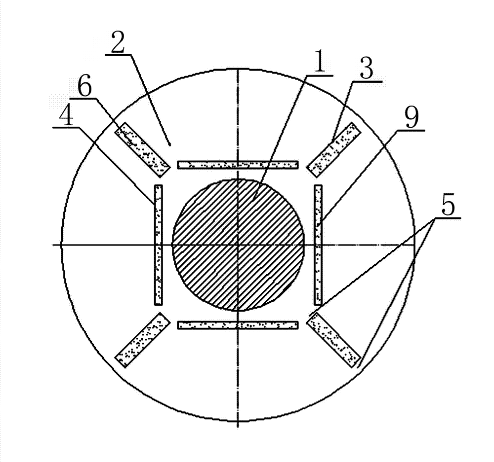
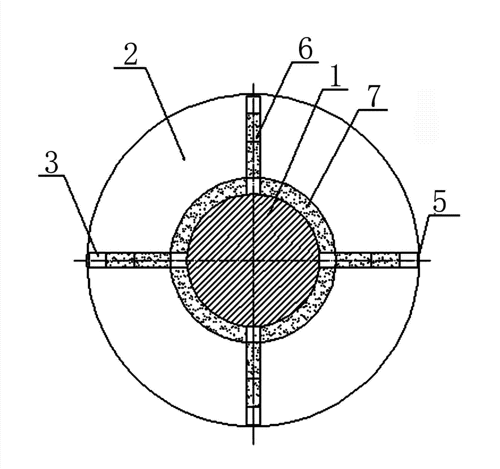
[0015] A hybrid permanent magnet synchronous motor rotor, comprising a steel shaft 1 and a rotor core 2; an even number of radial permanent magnet slots 3 are evenly distributed on the cross section of the rotor iron core 2; radial permanent magnet slots 3 are installed in each radial permanent magnet slot 3 Permanent magnet 6; even number of tile-shaped permanent magnets 7 are evenly distributed on the steel shaft 1 according to polarity, the polarities of two adjacent tile-shaped permanent magnets 7 are different, and there is a space between adjacent two tile-shaped permanent magnets 7 Gap; the inner end of each radial permanent magnet slot 3 has an opening, and each opening corresponds to each gap; the inner ring of the rotor core 2 is press-fitted on the outer surface of each tile-shaped permanent magnet 7;

[0016] The inner coercive force of the radial permanent magnet 6 closer to the center of the rotor iron core 2 is smaller, and the inner coercive force of the radial ...

Embodiment 2

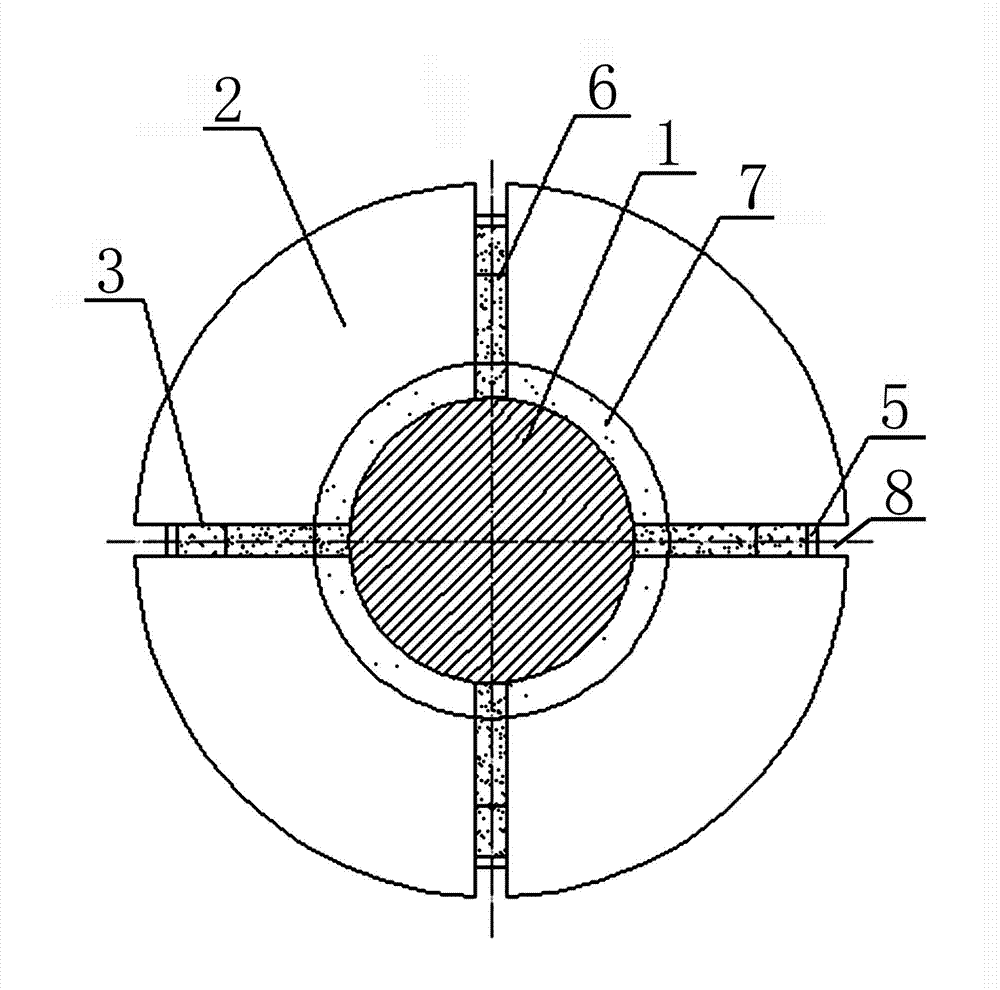
[0022] A hybrid permanent magnet synchronous motor rotor, comprising a steel shaft 1 and a rotor core 2; an even number of radial permanent magnet slots 3 are evenly distributed on the cross section of the rotor iron core 2; radial permanent magnet slots 3 are installed in each radial permanent magnet slot 3 Permanent magnet 6; even number of tile-shaped permanent magnets 7 are evenly distributed on the steel shaft 1 according to polarity, the polarities of two adjacent tile-shaped permanent magnets 7 are different, and there is a space between adjacent two tile-shaped permanent magnets 7 Gap; the inner end of each radial permanent magnet slot 3 has an opening, and each opening corresponds to each gap; the inner ring of the rotor core 2 is press-fitted on the outer surface of each tile-shaped permanent magnet 7;

[0023] The inner coercive force of the radial permanent magnet 6 closer to the center of the rotor iron core 2 is smaller, and the inner coercive force of the radial ...


PUM


Abstract

The invention relates to a permanent magnet synchronous motor, and in particular relates to a mixed permanent magnet synchronous motor rotor. The problems that the existing permanent magnet synchronous motor rotor is low in mechanical strength and high in magnetic leakage factor and the cost of the motor is high are solved. The mixed permanent magnet synchronous motor rotor comprises a steel shaft and a rotor core, wherein even radial permanent magnet slots are uniformly distributed on the section of the rotor core; a radial permanent magnet is arranged in each radial permanent magnet slot; even tile-shaped permanent magnets are uniformly distributed on the steel shaft according to the polarity; adjacent two tile-shaped permanent magnets have different polarities; a gap is reserved between adjacent two tile-shaped permanent magnets; the inner end of each radial permanent magnet slot is provided with an opening; each opening respectively corresponds to each gap; and the inner ring of the rotor core is pressed on the outer side face of each tile-shaped permanent magnet. The mixed permanent magnet synchronous motor rotor is suitable for various permanent magnet synchronous motors.

Description

technical field [0001] The invention relates to a permanent magnet synchronous motor, in particular to a hybrid permanent magnet synchronous motor rotor. Background technique [0002] A permanent magnet synchronous motor consists of a stator and a rotor. The magnetic circuit structure of the rotor of the permanent magnet synchronous motor can be divided into a radial magnetic circuit structure, a tangential magnetic circuit structure, and a hybrid magnetic circuit structure. In the prior art, the following problems generally exist in the rotor adopting the hybrid magnetic circuit structure: 1. The mechanical strength of the rotor is low. 2. The magnetic flux leakage coefficient of the rotor is large. 3. It fails to optimize the design of the radial permanent magnet according to the law of the reverse magnetic field acting in the rotor and the characteristics of the radial permanent magnet, thus resulting in high cost of the motor. [0003] The specific analysis is as foll...

Claims


Application Information

Patent Timeline
Patent Type & Authority Applications(China)
IPC IPC(8): H02K1/27
Inventor 岳群生
Owner 岳群生
Why Eureka
Try Eureka