
A Dynamic Electroluminescent Wire with Gradient Brightness

A technology of electroluminescent wire and electroluminescent material, which is applied in the direction of electroluminescent light source, electric light source, light source, etc., and can solve the problems that the change of luminous light intensity cannot be realized.

Active Publication Date: 2015-08-19
SHANGHAI KERUN PHOSPHOR TECH
View PDF3 Cites 0 Cited by
  • Summary
  • Abstract
  • Description
  • Claims
  • Application Information

AI Technical Summary

Problems solved by technology

[0003] Since the single-core or multi-core light-emitting wires in the prior art use a light-emitting layer and an insulating layer with a uniform thickness, their luminous intensity is consistent. Similar to festive string lights with directional jumps, the change of luminous light intensity cannot be realized from the device structure

Method used


Image

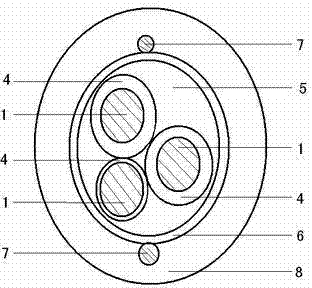
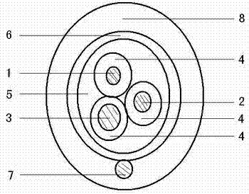
  • A Dynamic Electroluminescent Wire with Gradient Brightness
  • A Dynamic Electroluminescent Wire with Gradient Brightness

Examples


Embodiment

[0044] A round copper wire with a diameter of 0.12 mm is selected as the core wire electrode, and the number of core wire electrodes is 9.

[0045] The insulating layer is made by mixing and coating the dielectric material barium titanate and epoxy resin adhesive; the ratio between the dielectric material and the adhesive is about 1:1, and it is heated, dried and cured. The thicknesses of the outer coating insulation layers of the nine core wire electrodes are 0.03mm, 0.06mm, 0.09mm, 0.12mm, 0.15mm, 0.18mm, 0.21mm, 0.24mm, and 0.27mm, and the average spacing is 0.03mm.

[0046] 9 wires coated with insulating layer are twisted and twisted and arranged regularly to form a multi-strand wire, and then coated with a luminous layer on the surface.

[0047] The electroluminescent material layer is made by mixing and coating electroluminescent material D512 and epoxy resin adhesive. The ratio between electroluminescent material and adhesive is about 1:1, and it is heated, dried and cu...


PUM

PropertyMeasurementUnit
diameteraaaaaaaaaa
thicknessaaaaaaaaaa

Abstract

The invention relates to a dynamic electrogenerated emitting-light wire with gradual change of luminance, which comprises a plurality of core wire electrodes, insulating layers with different thicknesses, an electrogenerated emitting-light material layer, a transparent conducting layer, a transparent conducting layer electrode and a color transparent plastic layer, and is characterized in that the core wire electrodes are metal wires; the surfaces of the core wire electrodes are respectively provided with the insulating layers with different thicknesses; the core wire electrodes are spirally stranded and regularly arranged; the electrogenerated emitting-light material layer is uniformly coated on the surface; the transparent conducting layer is coated outside the electrogenerated emitting-light material layer, is in contact with the transparent conducting layer electrode, and is sealed by the color transparent plastic layer; and when the core wire electrodes, the transparent conducting layer electrode and a multichannel drive controller are connected correspondingly, the electrogenerated emitting-light wire generates dynamic direction flow, and meanwhile, the luminance is gradually increased or reduced.

Description

technical field [0001] The invention belongs to the technical field of electroluminescent wire application. Background technique [0002] The structure of the existing electroluminescent wire mainly includes a metal core electrode, an insulating medium layer, a luminous layer, a transparent conductive layer, and a wound external electrode. When the metal core electrode and the winding outer electrode are connected with a voltage of 80-110V, light will be produced. This structure, material, and formula have been clearly described in Chinese patents 200680032428.8 and 200410099233.8. The flashing of the luminous line uses a winding structure of multiple metal core electrodes. By controlling the opening and closing of the circuit, a single flashing multiple combination is completed, and the overall control is cycled segment by segment to achieve the effect of visual direction jumping, such as the Chinese patent 200510019319.X has been disclosed in detail. [0003] Since the s...

Claims


Application Information

Patent Timeline
Patent Type & Authority Patents(China)
IPC IPC(8): H05B33/14
Inventor 郑岩边静宇耿树范孟立建徐征
Owner SHANGHAI KERUN PHOSPHOR TECH
Learn More