Method for creating a sealed joint between aircraft parts

A technology for aircraft and components, applied in the field of aircraft structure, can solve problems such as complex installation, and achieve the effect of easy implementation

Inactive Publication Date: 2012-11-07
AIRBUS OPERATIONS (SAS)
View PDF6 Cites 4 Cited by
  • Summary
  • Abstract
  • Description
  • Claims
  • Application Information

AI Technical Summary

Problems solved by technology

This solution requires the addition of a large number of small, thin sheet metal pieces, which are complicated to install

Method used


Image

  • Method for creating a sealed joint between aircraft parts
  • Method for creating a sealed joint between aircraft parts
  • Method for creating a sealed joint between aircraft parts

Examples


Embodiment Construction

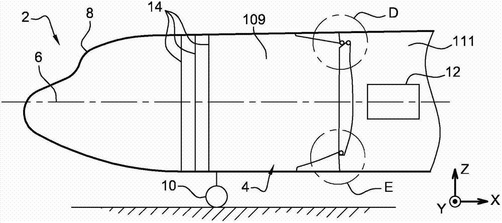
[0049] The aircraft shown in FIG. 1 is a heavy aircraft, more precisely an aircraft 2 . The aircraft 2 comprises a generally elongated cylindrical fuselage 4 with a horizontal axis 6 as the main axis of the fuselage. The front of the fuselage has a cockpit 8 . The aircraft is provided with wings (not shown) forming the wings, landing gear, a part 10 of which is visible in FIG. 1 , and an engine 12 .

[0050] In the following, reference is made to the X, Y, Z rectangular coordinate system, wherein the X, Y directions are horizontal and perpendicular to each other, the X direction is parallel to the axis 6, and the Z direction is vertical.

[0051] It is assumed here that the manufacture of aircraft 2 has been completed, or that the aircraft has in fact been flown. The practice is to install a removable sealed structural partition during the retrofit phase. The partition is designed to be airtight against the cabin pressure, which exists only on one side of the partition, in ...


PUM


Abstract

The invention relates to a method for creating a sealed joint (118) between elongate parts (14, 116) of an aircraft extending locally in main directions that are not mutually parallel; a plurality of parts of a mould are assembled on the parts; and a sealing material is injected into the mould.

Description

technical field [0001] The invention relates to aircraft structural parts, such as the fuselage. Background technique [0002] It is known to provide a structural partition inside the fuselage of an aircraft in order to divide the interior volume into two gastight or liquidtight regions. For example, one of the areas defined by the partition walls may be pressurized than the other area, or one of the areas may be used as a fuel tank. The junction between the partition wall and the fuselage wall is formed at an angle that is locally perpendicular to the wall and to components of the primary structure of the aircraft, including frames, stiffeners, stiffeners, beams, and the like. [0003] Such partition walls can be installed permanently when the aircraft is being built. It is however more appropriate to install such a partition during the retrofit phase, ie in an aircraft that was not originally designed to receive it. This is especially true for aircraft that are already ...

Claims


Application Information

Patent Timeline
Patent Type & Authority Applications(China)
IPC IPC(8): B29C70/84B29C65/70B29C45/14B64C1/06
CPCB29L2031/3082Y02T50/43B29C70/845Y02T50/42B29C45/14467B64C1/10B64C1/069B29K2083/00Y02T50/433B29L2031/3076B64C7/00B29C2045/1454B64C2001/0081B64C1/06Y02T50/40
Inventor F·达泽特
Owner AIRBUS OPERATIONS (SAS)
Why Eureka
Try Eureka