Golf club head and its manufacturing method

A technology for golf club heads and manufacturing methods, which is applied to golf balls, golf clubs, manufacturing tools, etc., which can solve the problems of increased difficulty in mechanical processing, increased cost, and increased cost required for mechanical processing, and achieve cost reduction , the effect of easy weight control

Inactive Publication Date: 2006-06-21
BRIDGESTONE SPORTS
View PDF1 Cites 0 Cited by
  • Summary
  • Abstract
  • Description
  • Claims
  • Application Information

AI Technical Summary

Problems solved by technology

[0003] However, when the metal parts are welded to each other by TIG welding or MIG welding, there is a problem that it is difficult to control the weight of the golf club head due to the use of welding rods and the occurrence of shrinkage cavities at the welding place.
[0004] In addition, when the metal parts are welded to each other by laser welding or electron beam welding, although there is no need to use welding rods, shrinkage cavities will not be produced at the welding place, and it is easy to control the weight of the golf club head. There is no gap, and it is necessary to perform precision machining of metal parts in advance, so there is a problem that the cost of machining of metal parts increases
In particular, when metal parts with different thicknesses are welded by laser welding or electron beam welding, the above-mentioned mechanical processing becomes more difficult, and the cost required for the mechanical processing of the metal parts increases significantly.

Method used


Image

  • Golf club head and its manufacturing method
  • Golf club head and its manufacturing method
  • Golf club head and its manufacturing method

Examples


no. 1 approach

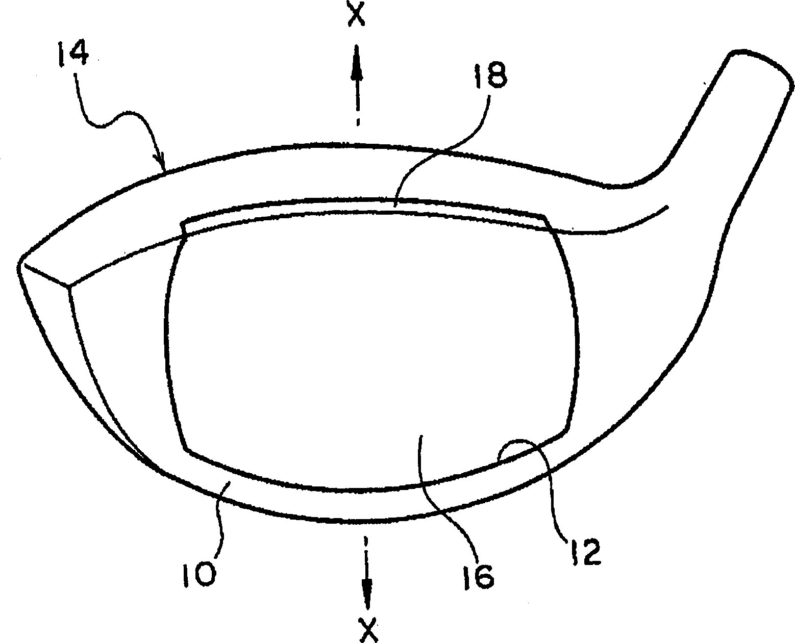
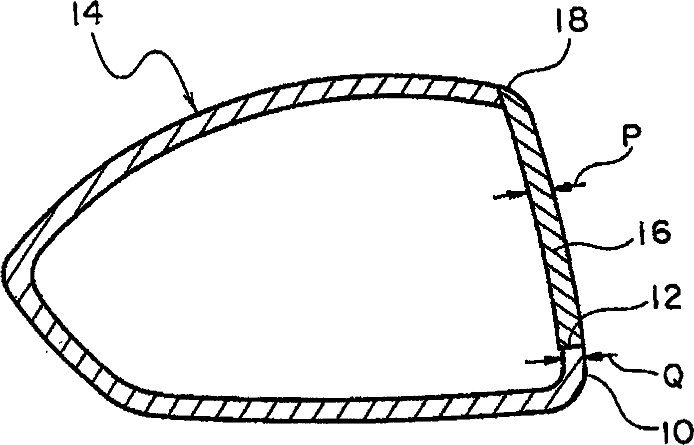
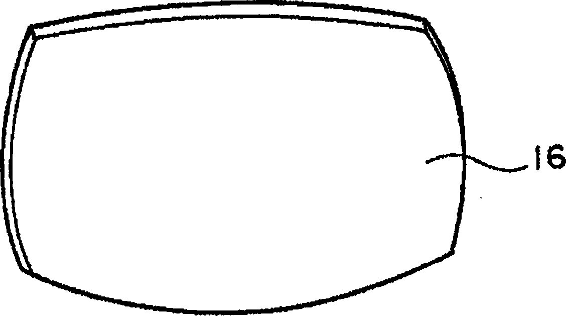
[0043] figure 1 It is a perspective view showing one embodiment of the golf club head according to the present invention. figure 2 is the edge of the same golf club head figure 1 The cross-sectional view of X-X line. image 3 It is a perspective view of the face parts of the same golf club head. The golf club head of this example is made as a wood golf club head having a hollow portion.

[0044] The golf club head of this example has a club head body 14 made of titanium alloy (specifically 6-4Ti) and a face part 16 made of titanium alloy (specifically Ti735), and the club head body 14 is formed on the ball striking face 10. There is a face opening 12 thereon, and the face member 16 is used to fill the face opening 12 .

[0045] In the golf club head of this example, the upper edge of the face opening 12 and the upper edge of the face member 16 extend to the crown. Therefore, when the face member 16 is fastened to the peripheral portion of the face opening 12 of the club ...

no. 2 approach

[0049] Figure 5 It is an exploded perspective view showing one embodiment of the golf club head according to the present invention. The golf club head of this example is made as an iron golf club head.

[0050] The golf club head of this example has a head body 34 (cast material of SUS630) and a face part 36 (rolled material of SUS630). The face member 36 is used to fill the face opening 32 .

[0051] In the golf club head of this example, when the face member 36 is fastened to the peripheral portion of the face opening 32 of the club head body 34, the upper edge 38 of the face member 36 becomes a part of the top plate of the golf club head, and the face member 36 The leading edge 40 of the golf club head becomes part of the nose.

[0052] In the golf club head of this example, the thickness of the face member 36 is made 0.1 mm thicker than the thickness of the peripheral portion of the face opening of the head body 34 .

[0053] In addition, in the golf club head of this...

no. 3 approach

[0055] Figure 6 It is a perspective view showing one embodiment of the golf club head according to the present invention. The golf club head of this example is made as an iron golf club head.

[0056] The golf club head of this example has a head body 52 (cast material of SUS630) and a face member 54 (rolled material of SUS630). not shown), the face part 54 is used to fill up the face opening. and, Figure 6 It shows that the head body 52 and the face member 54 are in a fastened state.

[0057] In the golf club head of this example, when the face member 54 is fastened to the peripheral portion of the face opening of the club head body 52, the lower edge 56 of the face member 54 becomes a part of the sole of the golf club head, and the front end of the face member 54 Edge 58 becomes part of the nose of the golf club head.

[0058] In the golf club head of this example, the thickness of the face member 54 is made 0.1 mm thicker than the thickness of the peripheral portion ...


PUM

PropertyMeasurementUnit
diameteraaaaaaaaaa
diameteraaaaaaaaaa

Abstract

The present invention provides a golf club head which has welding spots formed when metal parts having different thicknesses are welded by plasma welding, laser welding or electron beam welding, and it is not necessary to prevent the metal parts from producing each other during welding. Precise machining of metal parts in advance. Metal parts with different thicknesses, such as for the production of golf club heads welded by the club head body (14) and the face part (16), the gap between the club head body and the face part is filled with other metal materials (20) And welded by plasma welding, laser welding or electron beam welding.

Description

technical field [0001] The present invention relates to a golf club head and a manufacturing method thereof. The golf club head has welding spots formed when metal parts having different thicknesses are welded by plasma welding, laser welding or electron beam welding. Background technique [0002] Conventionally, as a golf club head in which metal parts are welded together to form welded joints, some have welded the face, crown, sole and neck with TIG welding, MIG welding, laser welding or electron beam welding (see Japanese Patent Application Laid-Open Publication No. Hei 5-15620). [0003] However, when the metal parts are welded to each other by TIG welding or MIG welding, there is a problem that it is difficult to control the weight of the golf club head due to the use of welding rods and the occurrence of shrinkage cavities at the welds. [0004] In addition, when the metal parts are welded to each other by laser welding or electron beam welding, although there is no n...

Claims


Application Information

Patent Timeline
Patent Type & Authority Applications(China)
IPC IPC(8): A63B53/04A63B102/32
CPCA63B53/0466A63B53/047A63B53/0475A63B2209/02B23K10/02B23K15/0073A63B2209/00B23K26/211B23K2103/05B23K2103/10A63B53/042A63B53/0408A63B53/0416A63B53/0458A63B53/0425
Inventor 今本泰范山岸久松永英夫
Owner BRIDGESTONE SPORTS
Why Eureka
Try Eureka