Diagnosis and treatment equipment

A technology of equipment and a diagnosis and treatment bed, which is applied in the field of diagnosis and treatment equipment that can alleviate patients' claustrophobia, can solve the problems of large display screen and high cost, and achieve the effect of low cost, simple structure and alleviating claustrophobia

Active Publication Date: 2012-11-14
SUZHOU INST OF BIOMEDICAL ENG & TECH
View PDF6 Cites 2 Cited by
  • Summary
  • Abstract
  • Description
  • Claims
  • Application Information

AI Technical Summary

Problems solved by technology

The disadvantage is that if the axial diagnosis and treatment hole of the medical equipment is longer, the required display screen will be larger and the cost will be higher

Method used


Image

  • Diagnosis and treatment equipment
  • Diagnosis and treatment equipment
  • Diagnosis and treatment equipment

Examples


Embodiment 1

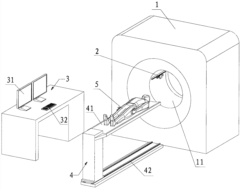
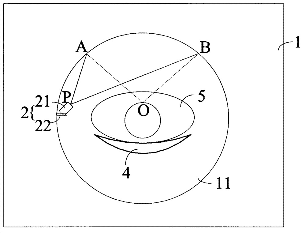
[0081] see figure 1 Shown is a schematic structural diagram of the diagnosis and treatment device in Embodiment 1 of the present invention. The diagnosis and treatment equipment includes a diagnosis and treatment equipment frame 1, a projection device 2 and a console 3, and a diagnosis and treatment hole 11 is provided on the diagnosis and treatment equipment frame 1, so that the patient 5 enters the diagnosis and treatment area during the diagnosis and treatment process. 5. The perception area located in the visual range of the patient 5 during diagnosis and treatment. The perception area is located at the top of the diagnosis and treatment hole 11. According to the definition of the diopter of the human eye, it is the range of the 5 human eyes of the patient at the top of the diagnosis and treatment hole. The preferred perception area is the visual range of the human eye. Degree 120°. The projection device 2 is set corresponding to the sensing area. In this embodiment, it i...

Embodiment 2

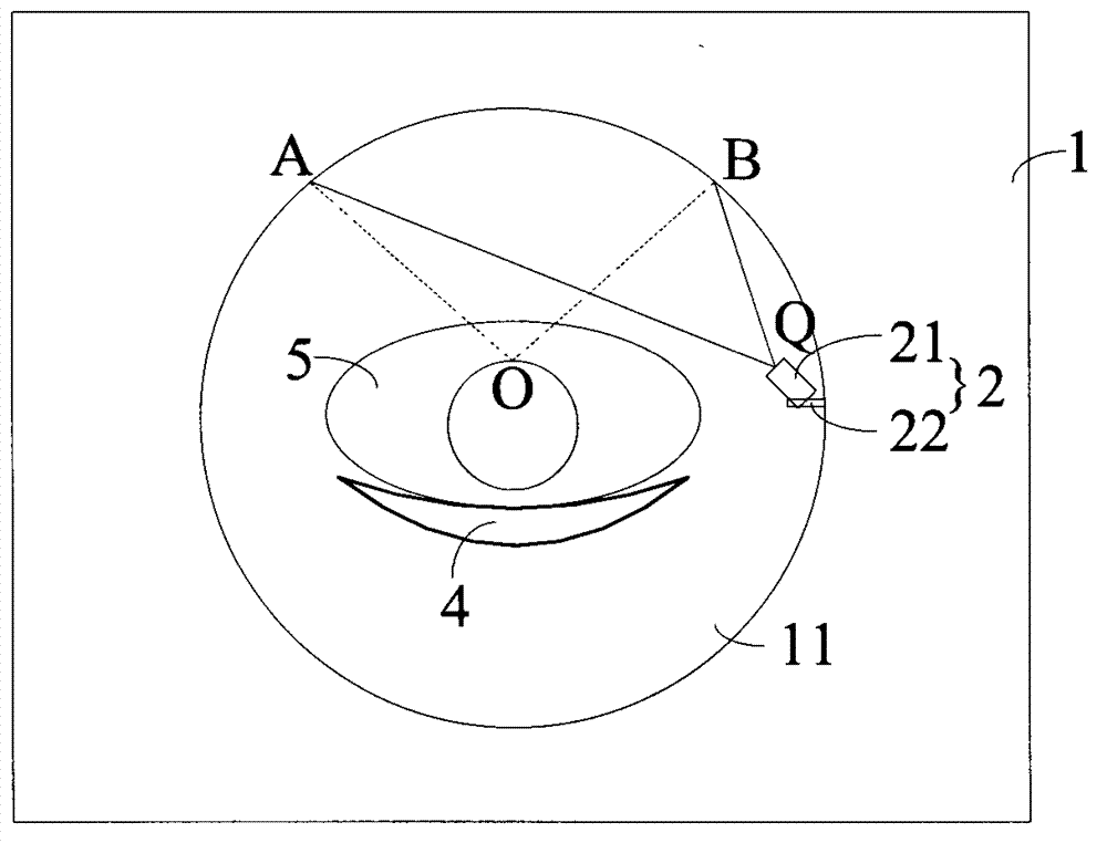
[0085] see image 3 As shown, it is a schematic diagram of the installation and projection of the projection device in the diagnosis and treatment equipment according to Embodiment 2 of the present invention. The difference between this embodiment and Embodiment 1 is: the projection device 2 is installed on the right side wall of the diagnosis and treatment hole 11, and the projection path QA>QB may also cause image distortion due to different projection paths. In order to ensure a good projection effect, Perform image preprocessing on videos or pictures through the console to offset the image distortion caused by different projection paths of videos or pictures. Other structures of the diagnosis and treatment equipment are the same as those in Embodiment 1, and will not be repeated here.

Embodiment 3

[0087] see Figure 4 as shown, Figure 4 It is a structural schematic diagram of the diagnosis and treatment equipment of Embodiment 3 of the present invention. The difference between this embodiment and Embodiments 1 and 2 is that the diagnosis and treatment equipment includes a set of projection devices, and a set of projection devices is provided with two projection devices 2, and the two projection devices 2 are respectively installed on the left side wall of the diagnosis and treatment hole 11 and right side wall. The two projection devices 2 respectively project half of the projected content, and the half of the content projected by the two projection devices 2 are spliced ​​into a complete content in the perception area. In other embodiments, multiple sets of such projection devices 2 can also be arranged along the axial direction of the diagnosis and treatment hole 11 according to actual projection requirements, so as to achieve a larger projection area, but this wil...


PUM


Abstract

The invention relates to the technical field of medical diagnosis and treatment equipment and provides diagnosis and treatment equipment. The diagnosis and treatment equipment comprises a diagnosis and treatment equipment rack used for realizing diagnosis and treatment functions; a diagnosis and treatment hole is arranged in the diagnosis and treatment equipment rack; the diagnosis and treatment equipment further comprises a projection unit and a control board; the projection unit is installed on the side wall of the diagnosis and treatment hole; and the control board is electrically connected with the projection unit and used for controlling the projection of the projection unit. The invention further provides diagnosis and treatment equipment, the projection unit of which is arranged onto a diagnosis and treatment bed. Through the arrangement of the projection unit, videos and pictures can be projected in diagnosis and treatment processes so that claustrophobia of a patient can be relieved.

Description

technical field [0001] The invention relates to the technical field of medical diagnosis and treatment equipment, in particular to a diagnosis and treatment equipment that can alleviate patients' claustrophobia. Background technique [0002] Some large-scale medical diagnosis and treatment equipment often need to send patients into the narrow and long diagnosis and treatment hole in the middle of the equipment. Such narrow and long diagnosis and treatment holes are likely to cause discomfort to patients, especially likely to induce claustrophobia in some patients, which will have a negative impact on diagnosis and treatment, and even cause interruption of diagnosis and treatment. Such as CT (Computed Tomography, computed tomography imaging), MRI (Magnetic Resonance Imaging, magnetic resonance imaging), PET / CT (Positron Emission Tomography / Computed Tomography, positron emission type computed tomography / computed tomography imaging, for PET Integrated equipment with CT), PET / M...

Claims


Application Information

Patent Timeline
Patent Type & Authority Applications(China)
IPC IPC(8): A61B5/16A61M21/00
Inventor 蒯多杰刘岿
Owner SUZHOU INST OF BIOMEDICAL ENG & TECH
Why Eureka
Try Eureka