
Magnetic roller with high field intensity

A magnetic roller and high-field technology, applied in high-gradient magnetic separators, magnetic separation, solid separation, etc., can solve the problems of small magnetic roller sweeping area and low magnetic separation efficiency, achieve simple structure, improve work efficiency, The effect of increasing the magnetic field

Active Publication Date: 2012-11-14
LIANYUNGANG BAOXIANG MACHINERY
View PDF5 Cites 6 Cited by
  • Summary
  • Abstract
  • Description
  • Claims
  • Application Information

AI Technical Summary

Problems solved by technology

[0002] The magnetic separator is a common magnetic separation equipment in the mineral processing field. The magnetic roller includes a magnetic cylinder, and there are several magnetic coils on the magnetic cylinder. The magnetic coils in the prior art are arranged perpendicular to the axis of the magnetic cylinder. The magnetic roller has a small scanning area and low magnetic separation efficiency

Method used


Image

  • Magnetic roller with high field intensity
  • Magnetic roller with high field intensity
  • Magnetic roller with high field intensity

Examples


Embodiment Construction

[0011] The specific technical solutions of the present invention will be further described below with reference to the accompanying drawings, so that those skilled in the art can further understand the present invention, without limiting their rights.

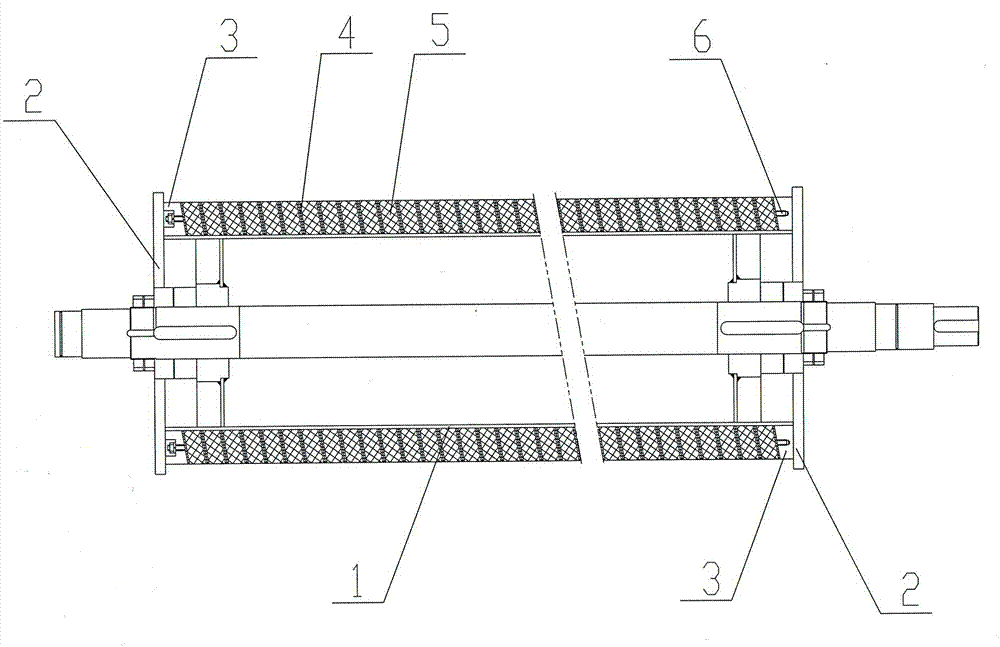
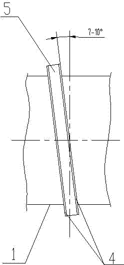
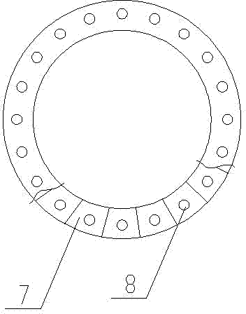
[0012] refer to figure 1 , a high-field-strength magnetic roller is provided with a magnetic roller body, the magnetic roller body is composed of a magnetic cylinder 1 and several magnetic coils 5 mounted on the magnetic cylinder 1, and flanges 2 are arranged at both ends of the magnetic cylinder 1, so The magnetic rings described above are installed between two flanges 2, and the polarities of the magnetic surfaces between adjacent magnetic rings are the same, and the magnetic rings include magnetic rings 5 ​​and magnetizing plates 4 arranged on both sides of the magnetic rings 5, The magnetic ring 5 is composed of several fan-shaped magnetic blocks 7; the included angle between the magnetic ring and the axis of the magnetic c...


PUM


Abstract

The invention relates to a magnetic roller with high field intensity. The magnetic roller is provided with a magnetic roller body, wherein the magnetic roller body consists of a magnetic cylinder and a plurality of magnetic coils arranged on the magnetic cylinder; flanges are arranged at the both ends of the magnetic cylinder; the magnetic coils are arranged between the two flanges; magnetic force faces between each adjacent magnetic coils have same polarity; each magnetic coil comprises a magnetic ring and magnetism increasing plates arranged on the both sides of the magnetic ring; each magnetic ring is formed by a plurality of fan-shaped magnetic blocks; an included angle between the axles of each magnetic coil and the magnetic cylinder is 7-10 degrees; a wedge-shaped substrate is arranged between the magnetic coils at both ends and the flanges; a plurality of positioning holes are uniformly formed along the periphery of each magnetic coil; the positioning holes on the adjacent magnetic coils correspond to one other and form a plurality of through holes along the axial direction of the magnetic cylinder; screw rods are arranged in the through holes; the both ends of each screw rod are fixedly connected with the flanges at the both ends of the magnetic cylinder; and a smooth roller face is formed on the surface of the magnetic roller body through machining. The magnetic roller is reasonable in structure, and the magnetic coils are arranged in an inclined manner, so that the scavenging area of the magnetic coils is enlarged, and the working efficiency of the magnetic roller is improved.

Description

technical field [0001] The invention relates to a magnetic roll of a permanent magnetic separator, in particular to a high-field magnetic roll. Background technique [0002] The magnetic separator is a common magnetic separation equipment in the mineral processing field. The magnetic roller includes a magnetic cylinder, and there are several magnetic coils on the magnetic cylinder. The magnetic coils in the prior art are arranged perpendicular to the axis of the magnetic cylinder. The magnetic roller has a small scanning area and low magnetic separation efficiency. Contents of the invention [0003] The technical problem to be solved by the present invention is to provide a high-field-strength magnetic roller with a reasonable structure and a large sweeping area of ​​the magnetic roller in view of the deficiencies of the prior art. [0004] The technical problem to be solved by the present invention is achieved through the following technical solutions. The present inven...

Claims


Application Information

Patent Timeline
Patent Type & Authority Applications(China)
IPC IPC(8): B03C1/02
CPCB03C1/025B03C1/0335B03C1/10
Inventor 袁友烈丁磷青肖龙海张顺才朱维成
Owner LIANYUNGANG BAOXIANG MACHINERY
Learn More