A valve upper structure

A head and valve body technology, used in lift valves, valve devices, engine components, etc., can solve the problems of cumbersome manufacturing and installation of gaskets, and the sealing ring cannot meet the requirements of durability and tightness, so as to avoid bending effects and simplify manufacturing. , the effect of reducing wear

Inactive Publication Date: 2012-11-14
FLUHS DREHTECHN
View PDF7 Cites 1 Cited by
  • Summary
  • Abstract
  • Description
  • Claims
  • Application Information

AI Technical Summary

Problems solved by technology

[0003] A disadvantage of the aforementioned known valve superstructure is that the manufacture of the gasket and its installation are very cumbersome
In addition, the seals used are increasingly unable to meet the increasingly stringent requirements for durability and tightness

Method used


Image

  • A valve upper structure

Examples


Embodiment Construction

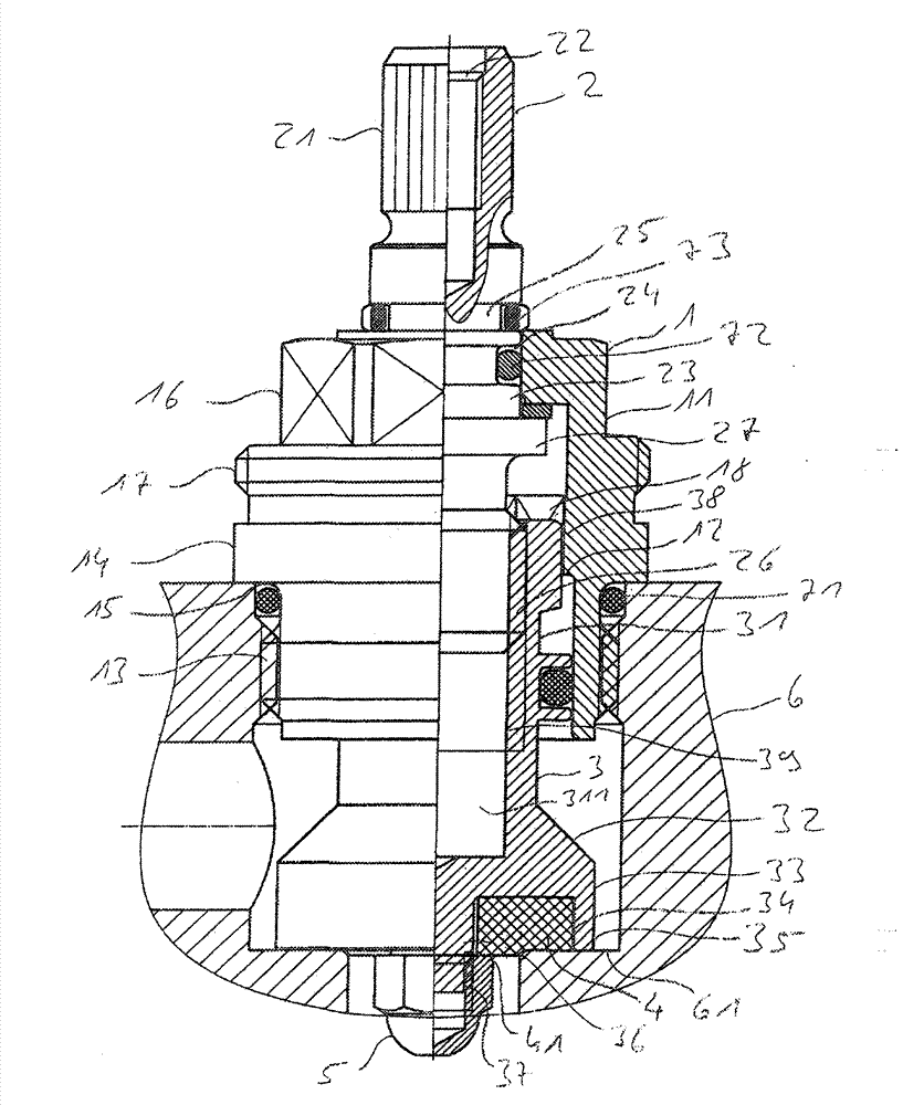
[0013] The valve superstructure chosen as embodiment has a head 1 which is penetrated in the middle by a mandrel 2 in which the mandrel passes radially. The valve body 3 is actuated via the spindle 2 and is in contact with the valve seat 61 of the housing 6 . The valve body 3 has a substantially cylindrical valve plunger 33 which carries a sealing gasket 4 which is surrounded by a peripheral edge 35 of a groove 34 which houses the sealing gasket 4, wherein the sealing gasket 4 and the groove The surrounding edge 35 of 34 is in contact with the valve seat 61 of the housing 6 .

[0014] The head 1 consists of a symmetrical hollow body which is open at both end faces. The head has a sleeve-like part 11 on its side facing the housing 6 . A stopper 12 for contacting the valve body 3 is formed on the inner periphery of the component 11 . The head 1 is provided with a connecting thread 13 on the outside of one end facing the housing 6 . The head 1 can be screwed into the housing ...


PUM


Abstract

The invention relates to a valve upper structure, comprising a head piece, a spindle centrally penetrating the head piece and a valve body actuatable via the spindle for attachment at a valve seat of a housing, wherein at the valve body, on its side directed away from the spindle, a sealing device is arranged. The sealing device comprises a substantially cylindrically designed valve plug which, concentric to the spindle axis, is provided with a groove which accommodates a sealing disc which projects beyond the height of the groove.

Description

technical field [0001] The invention relates to a valve superstructure (Ventiloberteil) according to the preamble of claim 1, having a head, a mandrel passing through the head in the middle and a contact housing actuatable by the mandrel. Valve body of the valve seat. Background technique [0002] Such a valve superstructure is known from GB2137736A. The valve superstructure serves to control the discharge of the medium from the fitting. For this purpose, the valve superstructure is screwed with its head into the housing of the fitting, on whose spindle a rotary handle or handle is fastened. To control the flow, a valve plunger is provided which is linearly displaceable inside the head via a spindle. For sealing against the valve seat, the valve plunger carries a gasket, which is fastened to the valve plunger by means of a nut or a shaped mushroom head and is provided with a hole which enables flushing (Hinterspülen) of the gasket from behind, thereby The gasket and the...

Claims


Application Information

Patent Timeline
Patent Type & Authority Applications(China)
IPC IPC(8): F16K1/46F16K1/36
CPCF16K1/46
Inventor F·图劳
Owner FLUHS DREHTECHN
Why Eureka
Try Eureka