Check patentability & draft patents in minutes with Patsnap Eureka AI!

Pilot valve with dual-function of mechanical and electric control for unloading valve for pump

An electromagnetic pilot valve and pilot valve technology, applied in the field of pilot valves, can solve the problems of occupying a large space, inconvenient maintenance, and difficult manufacturing, and achieve the effects of reducing the overall size, facilitating maintenance, and reducing manufacturing difficulty

Active Publication Date: 2012-11-14
BEIJING TIANMA INTELLIGENT CONTROL TECH CO LTD
View PDF4 Cites 0 Cited by
  • Summary
  • Abstract
  • Description
  • Claims
  • Application Information

AI Technical Summary

Problems solved by technology

However, the technical problem in the above technical solution is that installing an electronically controlled bypass switch valve in the pilot valve body is difficult to manufacture and inconvenient to maintain, and it needs to be connected with the electromagnetic pilot valve through a transition connecting plate, and the overall structure is relatively complicated. ; while the electronically controlled bypass switch valve is installed outside the pilot valve body, since the electromagnetic pilot valve is located below the electronically controlled bypass switch valve, it not only takes up a lot of space, but it is also inconvenient to maintain the electromagnetic pilot valve from the bottom

Method used


Image

  • Pilot valve with dual-function of mechanical and electric control for unloading valve for pump
  • Pilot valve with dual-function of mechanical and electric control for unloading valve for pump

Examples


Embodiment Construction

[0038] Specific embodiments of the present invention are provided below in conjunction with the accompanying drawings.

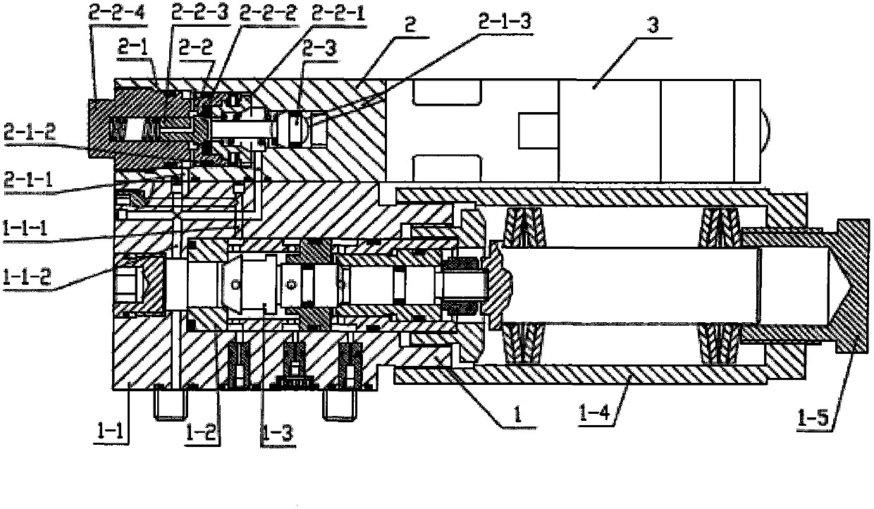
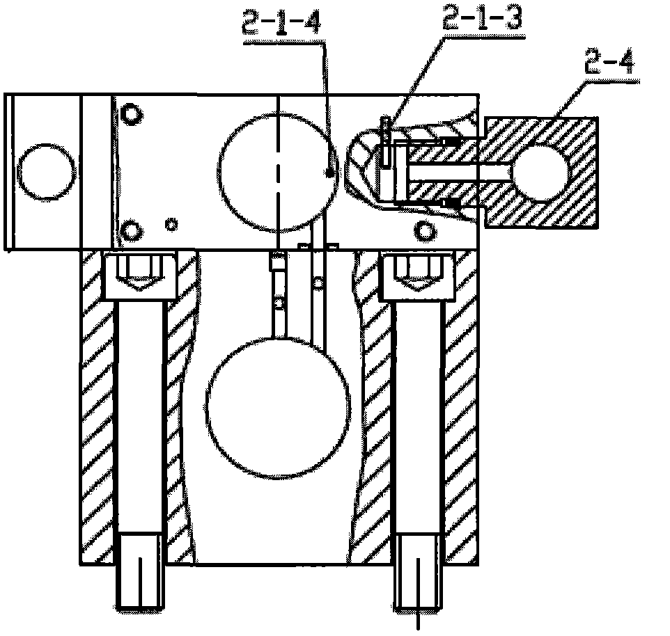
[0039] As shown in the accompanying drawings, the present invention includes a mechanical pilot valve 1, an auxiliary valve 2 functioning as an electronically controlled bypass switching valve, and an electromagnetic pilot valve 3. The mechanical pilot valve 1 includes a valve body 1-1 and a valve seat 1-2. , spool 1-3, spring sleeve 1-4 and pressure regulating screw 1-5, the first liquid channel 1-1-1 of the valve body communicated with the useful process hole is processed on the valve body 1-1 and the process The hole communicates with the second liquid channel 1-1-2 of the valve body. On the back of the mechanical pilot valve 1, the auxiliary valve 2, which acts as an electronically controlled bypass switch valve, is connected with screws. The auxiliary valve 2 includes the auxiliary valve body 2-1 , Cartridge spool 2-2 and auxiliary valve ejector rod 2-3...


PUM


Abstract

The invention discloses a pilot valve with dual-function of mechanical and electric control for an unloading valve for a pump, in order to overcome the problems that the pilot valve of the existing unloading valve for a pump is complex in structure, is high in manufacturing difficulty, and is inconvenient to maintain. The pilot valve with dual-function of mechanical and electric control for the unloading valve for the pump is characterized in that a valve body first liquid channel and a valve body second liquid channel are machined on a valve body of the mechanism pilot valve; the back side of the mechanical pilot valve is connected with an auxiliary valve; an electromagnetic pilot valve is installed on the auxiliary valve; and an auxiliary valve body first liquid channel, an auxiliary valve body second liquid channel and an auxiliary valve liquid supplying hole are machined on the auxiliary valve body. The pilot valve with dual-function of mechanical and electric control for the unloading valve for the pump has the beneficial effects that on the basis that the coexistence of electric control and liquid control as well as empty loading starting and empty loading pump stopping are realized, the integral dimension of the valve is shortened further, and convenience is brought about for the maintenance; because the auxiliary valve is individual out of the mechanical pilot valve, the manufacturing difficulty is lowered; also because the auxiliary valve is individual out of the mechanical pilot valve, whether the fault is generated on the auxiliary valve or the mechanical pilot valve is easy to determine; and because a valve core of the auxiliary valve is an inserted valve core, the pilot valve with dual-function of mechanical and electric control for the unloading valve for the pump is convenient to maintain.

Description

technical field [0001] The invention belongs to the technical field of pumping station control equipment, and in particular relates to a pilot valve with dual functions of mechanical and electric control, which is used for an unloading valve of a coal mine emulsion pumping station. Background technique [0002] The pilot valve of the hydraulic control unloading valve in the prior art emulsion pumping station consists of a valve body, a valve seat, a valve core, a booster piston, a strong spring, a pressure introduction throttle plug, a pump inlet liquid throttle plug, and a control piston. The pilot valve of this hydraulic control structure can only realize hydraulic control unloading, and the pressure fluctuation value is relatively large. At the same time, the pilot valve of this structure cannot realize no-load start and no-load stop pump, and manpower is required to adjust the pressure. control. In the prior art, there is also a mechanism that installs hydraulically con...

Claims


Application Information

Patent Timeline
Patent Type & Authority Applications(China)
IPC IPC(8): F16K31/02F16K31/12
Inventor 李继周
Owner BEIJING TIANMA INTELLIGENT CONTROL TECH CO LTD
Features
  • R&D
  • Intellectual Property
  • Life Sciences
  • Materials
  • Tech Scout
  • Unparalleled Data Quality
  • Higher Quality Content
  • 60% Fewer Hallucinations
Learn More