A gate driving circuit, method and liquid crystal display

A gate drive circuit and gate technology, applied in the field of liquid crystal displays and gate drive circuits, can solve problems such as failure, large jump voltage, affecting the picture quality of the TFT panel, etc., so as to improve the picture quality and reduce the jump voltage. Effect

Active Publication Date: 2015-08-05
BEIJING BOE OPTOELECTRONCIS TECH CO LTD
View PDF8 Cites 0 Cited by
  • Summary
  • Abstract
  • Description
  • Claims
  • Application Information

AI Technical Summary

Problems solved by technology

[0007] However, once the temperature compensation method is used to ensure the effectiveness of the gate drive circuit, the Vgh voltage may rise above 30V, and the DC / DC IC cannot withstand such a high voltage. At this time, the MLG function will fail
Once the MLG function fails, there will be a large jump voltage at the moment when the TFT is turned off, which will affect the picture quality of the TFT panel.

Method used


Image

  • A gate driving circuit, method and liquid crystal display
  • A gate driving circuit, method and liquid crystal display
  • A gate driving circuit, method and liquid crystal display

Examples


Embodiment Construction
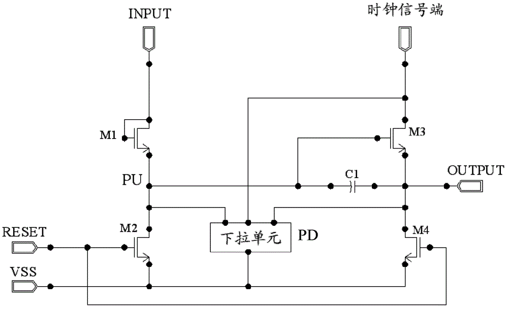
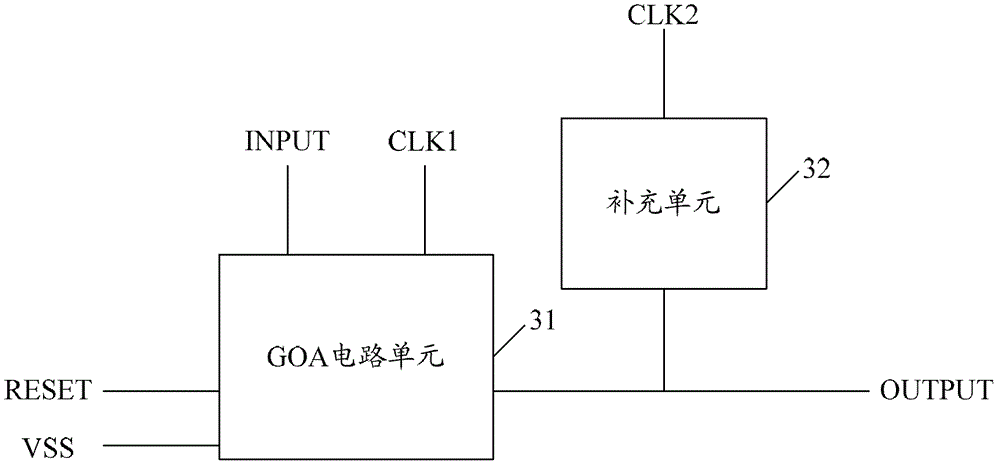
[0040]The basic idea of ​​the present invention is: the gate drive circuit includes a multi-stage shift register, wherein each stage of the shift register includes a pull-up driving unit, a pull-up unit, a reset unit, a pull-down unit, and also includes: a supplementary unit; wherein , the pull-up unit is used to use the clock signal of the first clock terminal as the output of the shift register of this stage when it is turned on; the supplementary unit is connected to the pull-up unit and is used to turn on the second The clock signal at the clock end is used as the output of the shift register of this stage.

[0041] In order to make the objectives, technical solutions and advantages of the present invention more clearly understood, the present invention will be further described in detail below with reference to the accompanying drawings and embodiments.

[0042] image 3 The functional structure of each stage of the shift register in the gate drive circuit of the present...


PUM


Abstract

The present disclosure provides a gate driving circuit, a gate driving method and a liquid crystal display. Said gate driving circuit includes shift registers at a plurality of stages, wherein the shift register at each stage includes a pull-up driving unit, a pull-up unit, a reset unit, a pull-down unit and a supplementary unit; said pull-up unit is used for making a clock signal at a first clock terminal an output signal of the shift register at the present stage when being turned on; said supplementary unit, connected to said pull-up unit, is used for making a clock signal at a second clock terminal the output signal of the shift register at the present stage when being turned on. With the supplementary unit of the shift register at each stage in the gate driving circuit, the present disclosure controls the output of the shift register through turning on the supplementary unit at the instant of the TFT being turned off, which can reduce voltage jump of a pixel, achieve the MLG function and enhance the picture quality of the LCD.

Description

technical field [0001] The present invention relates to gate driving technology, in particular to a gate driving circuit, method and liquid crystal display. Background technique [0002] Liquid crystal displays are currently commonly used flat panel displays, among which thin film field effect transistor liquid crystal displays (Thin Film Transistor Liquid Crystal Display, TFT-LCD) are currently the mainstream products in liquid crystal displays. With the increasingly fierce competition of TFT-LCD products, various manufacturers have adopted new technologies to reduce the cost of products and improve the market competitiveness of products. Among them, the GOA (Gate on Array) technology refers to integrating the gate driver (Gate Driver) of the TFT-LCD on the array substrate to form the scanning drive for the panel. Compared with the traditional chip-on-flex / film (COF) and direct bonding on glass (Chip-on-glass, COG) processes, it can not only save costs, but also the panel ...

Claims


Application Information

Patent Timeline
Patent Type & Authority Patents(China)
IPC IPC(8): G09G3/36
CPCG09G3/3677G09G2320/041G09G2320/0223G11C19/28G09G2310/0286G09G3/3611G09G3/36
Inventor 陈希崔文海
Owner BEIJING BOE OPTOELECTRONCIS TECH CO LTD
Why Eureka
Try Eureka