
Welded gearshift linkage

A shift lever and shift fork technology, which is applied in the field of shift levers, can solve problems such as the weight of shift tubes, and achieve the effects of reducing processing time, saving costs, and saving parts and working steps

Active Publication Date: 2012-11-14
KOKI TECHN TRANSMISSION SYST
View PDF11 Cites 2 Cited by
  • Summary
  • Abstract
  • Description
  • Claims
  • Application Information

AI Technical Summary

Problems solved by technology

This case has the disadvantage that the transmission tube is heavy, since a large wall thickness is required

Method used


Image

  • Welded gearshift linkage
  • Welded gearshift linkage
  • Welded gearshift linkage

Examples


Embodiment Construction

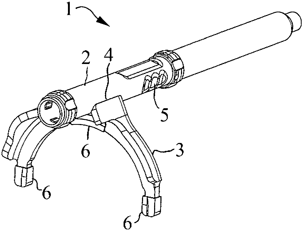
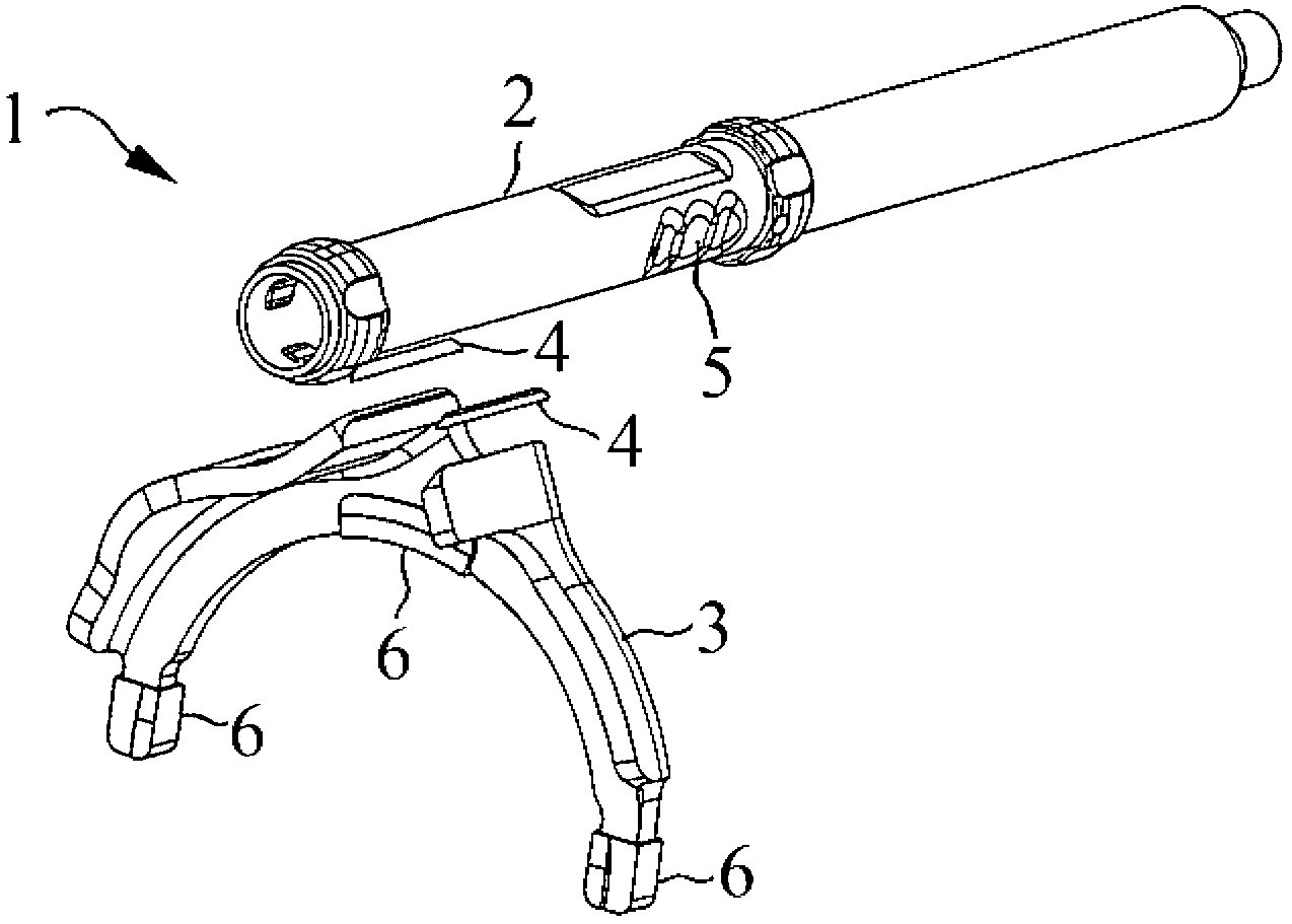
[0023] figure 1 A selector lever 1 according to the invention is shown in , which comprises a transmission tube 2 and a selector fork 3 . The shift fork 3 passes through two laser welded seams 4 (in figure 1 Only one weld 4) is shown in the figure to connect with the transmission tube 2.

[0024] The transmission tube 2 also has a detent contour 5 which is machined into the transmission tube 2 by rotary forging. The wall thickness of the transmission tube 2 can be limited to 1.5 mm by machining the detent contour 5 by rotary forging. With the directly welded connection of the selector fork 3 to the transmission tube 2 , a considerable weight saving is thereby achieved compared with conventional transmission tubes. It should also be pointed out that a plastic pad 6 is provided on the selector fork 3 and is intended to rest against other transmission components.

[0025] exist figure 2 shown again in a perspective, schematic exploded view figure 1 Shown is the selector le...


PUM

PropertyMeasurementUnit
thicknessaaaaaaaaaa

Abstract

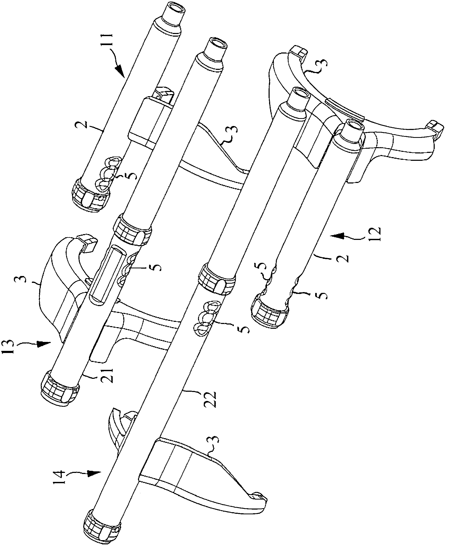
The invention relates to a gearshift linkage (1, 11-14), in particular for a motor vehicle gearbox, comprising a shifting fork (3) and a gearshift tube (2, 21, 22), wherein the gearshift tube (2, 21, 22) is welded to the shifting fork (3) by means of laser welding.

Description

technical field [0001] The invention relates to a selector lever according to the preamble of claim 1 and to a method for producing a selector lever according to the accompanying method claims. Background technique [0002] Selector levers are known from the prior art, in which a transmission tube and a selector fork are connected to one another via a sleeve. One possibility for connecting the sleeve to the selector fork is to fasten the sleeve to the transmission tube by means of a clamping connection. A disadvantage of this connection technique and other known connection techniques is that they are labor-intensive and expensive due to the additional components. In addition, additional components bring about additional weight, so that such selector levers are relatively heavy. [0003] With regard to the shift tube, it should also be pointed out that since the detent contours are produced in the detent by milling, the detent must have a relatively high wall thickness, so ...

Claims


Application Information

Patent Timeline
Patent Type & Authority Applications(China)
IPC IPC(8): B23K26/24F16H63/30
CPCF16H63/38F16H63/32G06F3/0202B23K2201/006F16H63/30F16H2063/321F16H2063/3079B23K26/243B23K26/242B23K2101/006
Inventor 伯恩特·舒尔茨马尔库斯·普赖泽尔
Owner KOKI TECHN TRANSMISSION SYST
Learn More