Printing ink stirrer for offset lithography

A technology of lithographic offset printing and mixer, which is applied in the direction of mixer accessories, mixers, dissolution, etc., can solve the problems of heavy weight, labor, and poor effect of removing air bubbles, and achieve the effect of improved efficiency and strong practicability

Inactive Publication Date: 2012-11-21
苏州市博来特油墨有限公司
View PDF3 Cites 4 Cited by
  • Summary
  • Abstract
  • Description
  • Claims
  • Application Information

AI Technical Summary

Problems solved by technology

The existing method generally requires two separate equipment, the mixer and the vacuum pump, but the mixing tank is generally made of metal, and the weight is very heavy. The steps of constantly moving the position for stirring and vacuum pumping are very laborious. not good

Method used


Image

  • Printing ink stirrer for offset lithography

Examples


Embodiment Construction

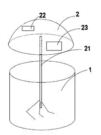
[0010] An ink mixer for lithographic offset printing, such as figure 1 As shown, consistent with the prior art, the mixer includes a mixing tank 1 on which a cylinder cover 2 is sealed. The cylinder head 2 is provided with a stirring rod 21, and the stirring rod 21 passes through the cylinder head 2 and is connected to a motor above the cylinder head 2 (not shown in the figure). The cylinder head 2 also includes a vacuum device, the vacuum device includes a vacuum pump, and the vacuum tube 22 of the vacuum pump is fixed on the cylinder head 2 . Such a structure can be vacuumed while stirring, avoiding the prior art of first stirring and then vacuuming. The efficiency is higher, and in order to better observe the vacuuming situation, a transparent visible window 23 for observation is provided on the cylinder head 2 .

[0011] The present invention still has many specific implementation modes, and all technical solutions formed by adopting equivalent replacement or equivalent ...


PUM


Abstract

The invention provides a printing ink stirrer which comprises a stirring cylinder; a cylinder cover is hermetically arranged on the stirring cylinder; a stirring rod is arranged on the cylinder cover; a vacuum pumping device is further arranged on the cylinder cover; the vacuum pumping device comprises a vacuum pump; a vacuum pumping pipe of the vacuum pump is fixed on the cylinder cover; and a transparent and visible window for observation is arranged on the cylinder cover. The printing ink stirrer has the benefit that through the combination of stirring and vacuum pumping, the efficiency is greatly improved, and the practicality is high.

Description

technical field [0001] The invention relates to an agitator, in particular to an ink agitator for lithographic offset printing with high efficiency and capable of vacuuming. Background technique [0002] The production process of lithographic offset printing ink is generally as follows: configure the raw materials according to the formula, disperse and stir the raw materials in the mixer, add diluents, etc. to dilute, and finally adjust the viscosity of the ink through a three-roller machine, and finally pack it in cans. In order to ensure the quality of the ink, constant vacuuming is required during the stirring process to remove air bubbles. The existing method generally requires two separate equipment, the mixer and the vacuum pump, but the mixing tank is generally made of metal, and the weight is very heavy. The steps of constantly moving the position for stirring and vacuum pumping are very laborious. not good. Contents of the invention [0003] The object of the pr...

Claims


Application Information

Patent Timeline
IPC IPC(8): B01F13/06B01F15/00
Inventor 徐建明徐晓花
Owner 苏州市博来特油墨有限公司
Why Eureka
Try Eureka