Laser marking machine

A laser marking machine and laser technology, applied in the field of marking machines, can solve problems such as unstable performance, poor marking quality, and complex structure, and achieve the effects of compact structure, convenient operation, and high marking efficiency

Inactive Publication Date: 2012-11-21
SUZHOU INDAL PARK TAIGE ELECTRONICS SCI &TECH
View PDF8 Cites 8 Cited by
  • Summary
  • Abstract
  • Description
  • Claims
  • Application Information

AI Technical Summary

Problems solved by technology

Although the utility model can mark a large area, it still has the defects and problems of complex structure, unstable performance and poor marking quality

Method used


Image

  • Laser marking machine

Examples


Embodiment Construction

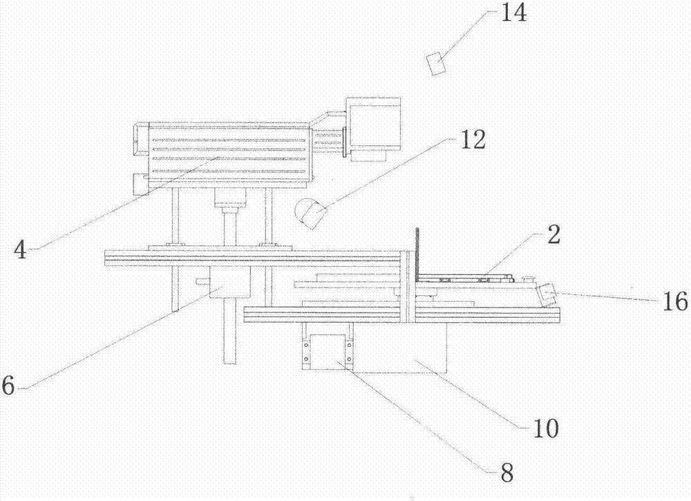
[0016] like figure 1 As shown, a laser marking machine of the present invention includes a workbench 2, a laser 4, an elevator 6 and a working motor 8, wherein the laser 4 is installed above the workbench 2, and the elevator 6 is installed below the laser 4 for driving The laser 4 moves up and down, and the working motor 8 is installed under the workbench 2 and is connected to the workbench 2 through a divider 10 . In actual use, in order to keep the working environment clean, a fume extraction device 12 is installed above the workbench 2. The fume extraction device 12 can promptly remove the fume generated during laser marking, thereby maintaining a cleaner working environment. At the same time, in order to improve the operation safety of the laser marking machine, a No. 1 safety grating 14 and a No. 2 safety grating 16 are installed on the top and side of the workbench 2 respectively. In case of misoperation, the laser marking machine can be stopped in time, so as to achiev...


PUM


Abstract

The invention discloses a laser marking machine, which comprises a workbench (2) and a laser (4) arranged above the workbench (2) and is characterized by comprising an elevator (6) and a working motor (8), wherein the elevator (6) is installed below the laser (4) and is used for driving the laser (4) to reciprocate, and the working motor (8) is installed below the workbench (2) and is in transmission connection with the workbench (2) by a splitter (10). The laser marking machine has the advantages of simple structure, stable performance and better marking quality.

Description

technical field [0001] The invention relates to a marking machine, in particular to a laser marking machine. Background technique [0002] With the development of modern technology, laser products have been applied in more and more industries. Among them, the laser marking machine is widely promoted and applied due to its inherent advantages of fast speed, low consumption, and environmental protection. [0003] The Chinese patent authorization announcement number is 201086459Y, and the utility model patent whose authorization announcement date is July 16, 2008 discloses a laser marking machine, including a laser device, a beam expander lens group, a vibrating lens, an F-θ lens group, and a computer. The control device, the workbench, is characterized in that it controls the PCI interface embedded in the PC, controls the scanning vibrating mirror through software, the workbench is a mobile platform, and the X and Y axes of the mobile workbench are controlled by the control c...

Claims


Application Information

Patent Timeline
Patent Type & Authority Applications(China)
IPC IPC(8): B41J2/435B41J3/407
Inventor 张鑫严小斌薛振江
Owner SUZHOU INDAL PARK TAIGE ELECTRONICS SCI &TECH
Why Eureka
Try Eureka