Sensing element with plurality of magnet blocks uniformly distributed in housing

A technology with uniform distribution and sensing elements, which is applied to vehicle components, instruments, speed/acceleration/shock measurement, etc., can solve the problems of motor running unstable, not getting power assistance, running unstable, etc., and achieves low cost and good structure Simple, signal-meaning-accurate effects

Inactive Publication Date: 2012-11-21
CHENGDU KUANHE TECH +3
View PDF6 Cites 1 Cited by
  • Summary
  • Abstract
  • Description
  • Claims
  • Application Information

AI Technical Summary

Problems solved by technology

[0013] Disadvantages (1) Using two permanent magnets with no difference to represent the fixed positions of the two pedals, only multiple Halls can be used to represent the pedals Rotation position: There is no difference between the two permanent magnets. The advantage is that the fixed positions of the two pedals can be expressed regardless of the left and right feet, so that the left and right feet can generate power assistance requirements, which can produce the same motor power assistance effect; but the disadvantage is that The permanent magnetic steel itself cannot indicate the rotation position of the pedal, but can only use multiple Halls at different corner positions to indicate the rotation position of the pedal, so it is not possible to use only one Hall, but must use multiple Halls
[0014] Disadvantage (2) Only one Hall cannot be used, and three Halls will inevitably cause the original segmentation error of the three control signals, which will distort the power-assist demand model, naturally The generation of power output is inconsistent with the demand for power assistance: no matter whether the power-assisted bicycle has one or two motors, the sensor signal for controlling the motor can only be controlled by using one sensor signal input to the motor controller; and the patent uses three sensors. If Hall controls the motor, the three control signals of the three Halls must be combined into one combined control signal before it can be input to the motor controller
The sensing parameters of the three Halls cannot be the same, especially due to changes in ambient temperature and long-term use, the sensing parameters of the three Halls may vary greatly. The output voltages are different, resulting in different power output of the motor, and the power output is inconsistent with the power demand; similarly, when the power demand is the same, the outputs of different Halls may be the same voltage, resulting in the same power output of the motor, and also There is a problem that the power output is inconsistent with the power demand
[0015] Disadvantages (3) The combined control signal is prone to signal drift, which makes the combined control signal not match the motor controller, and the power-assisted demand model is distorted: due to changes in ambient temperature and use time After a long period of time, the sensing parameters of the three Halls may vary greatly, and the connection points of the three control signals of the three Halls will inevitably change, so the combined control signals generated by the same boosting demand will produce segmental signal drift. Combining the control signals as a whole produces signal distortion, that is, the power-assist demand model is distorted, causing the motor controller to choose any one of the three control signals as a reference, which will cause the problem that the power-assisted output is inconsistent with the power-assisted demand
[0016] Disadvantage (4) The sensing points cannot be increased arbitrarily. If there are too few sensing points, the motor will not run smoothly, making the rider feel very uncomfortable: due to the disadvantages (1) and (2) are the most important The number of halls is greater than one. Obviously, the more the number of halls, the more serious the shortcomings (1) and (2) are.
Therefore, the power-assisted bicycle provided by this patent can only be a very bad power-assisted bicycle that makes the rider feel comfortable.
[0017] Disadvantages (5) The signal blind area reaches 42 degrees, and when the power is needed when starting, it is impossible to get it: as we all know, the moment of a person pedaling on a bicycle is the smallest at the apex , from the angle of 10-45 degrees away from the top is the area that needs the most assistance, but the angle between the Halls in this patent is 42.5-43.5 degrees, and there is no Hall in the area of ​​10-42 degrees away from the top of the pedal. There is no control signal, and the result is when the assist is most needed, but the motor of the assist bicycle cannot assist
[0018] In short, this patent is a technical solution for using multiple Halls to control the booster mode, because only multiple Halls can be used to represent the rotation position of the pedal, and the multiple control signals of multiple Halls must have original errors, and the combined control signals It is also easy to produce signal drift, which can cause distortion of the assist demand model, that is, the same assist demand at different times, but different assist effects; the more the number of Halls, the more serious the distortion of the assist demand model, limiting the number of Halls , a small amount of Hall will cause the motor to run unsteadily, making the rider feel very uncomfortable, and will not get assistance when starting
To make it undistorted to help the demand model, and to ensure the smooth operation of the motor, there are always two issues. It is impossible to have both.

Method used


Image

  • Sensing element with plurality of magnet blocks uniformly distributed in housing
  • Sensing element with plurality of magnet blocks uniformly distributed in housing
  • Sensing element with plurality of magnet blocks uniformly distributed in housing

Examples


Embodiment 1

[0046] Embodiment 1. A sensor element with evenly distributed multi-magnetic blocks in the housing

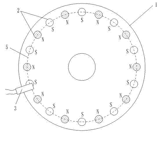
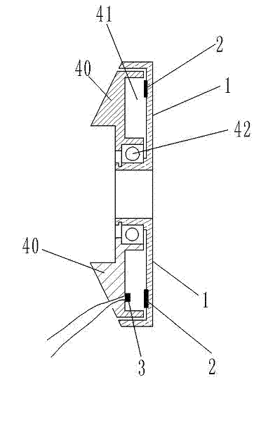
[0047] Such as figure 1 , 3 , with the concave surfaces of an annular groove rotating disk 1 and an annular groove fixing disk 40 facing each other, the size of the annular groove rotating disk 1 and the annular groove fixing disk 40 just makes the annular groove fixing disk 40 fit in In the annular groove of the annular groove rotating disk 1, two disks are synthesized into a fitting inner hollow shell that can rotate relatively, and the concave surfaces of the two disks are sandwiched into a hollow ring 41; the annular groove rotating disk at the position of the hollow ring 41 1 is fixedly provided with 20 permanent magnet blocks 2. The annular groove rotating disk 1 and the annular groove fixed disk 40 are injection molded with high-strength plastics.

[0048] The diameter of the annular groove rotating disc 1 in the hollow ring 41 is 10.0 cm, and 20 permanent magnet bloc...

Embodiment 2

[0053] Embodiment 2. Sensing elements with evenly distributed multi-magnetic blocks in a high-density housing

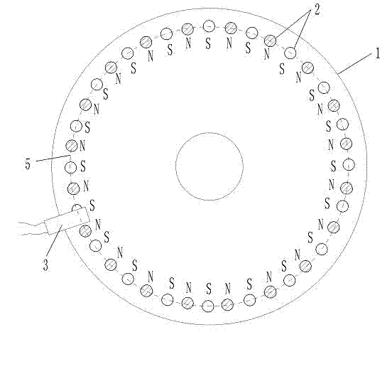
[0054] Such as figure 2 , 3 , the diameter of the annular groove rotating disk 1 in the hollow ring 41 is 10.0 centimeters, and 40 permanent magnet blocks 2 are established on the annular groove rotating disk 1. The diameters of the 40 permanent magnet blocks 2 are respectively 0.6 centimeters, and the magnetic flux is 146- --279(B·H)max / KJ·m -3 one of the values ​​in . Hall 3 keeps a distance of 0.2 cm from each permanent magnet 2 in the rotating state, so that when each rotating permanent magnet 2 passes through Hall 3, Hall 3 can generate a corresponding rectangular wave electric signal output. The structures of other rotating disk 1, permanent magnet block 2, and Hall 3 are the same as those in embodiment 1.


PUM


Abstract

The invention discloses a sensing element with a plurality of magnet blocks uniformly distributed in a housing, belongs to the technical field of signal providing magnetic induction, and particularly relates to a technology for providing a control signal with multi-point magnetic induction on a rotating component. A plurality of permanent magnets and Halls are arranged in cavities embedded in a rotation plate and a fixed plate; the permanent magnets are fixedly arranged on the rotation plate and distributed to form a ring-shaped structure in such a manner that the adjacent magnetic polarities of the permanent magnets are opposite, that is, the distribution manner is N pole, S pole, N pole and so on; and the Halls on the fixed plate are arranged in positions near the permanent magnets. The sensing element has the advantages that as the adjacent magnetic polarities of the permanent magnets are opposite, that is, the distribution manner is N pole, S pole, N pole and so on, the Halls can acquire rectangular wave signals, and digital processing can be conducted on the rectangular wave signals conveniently; and the positions of the permanent magnets and the Halls are fixed relatively, so that signals can be output reliably.

Description

technical field [0001] The invention belongs to the technical field of providing signals by magnetic induction, and in particular relates to the technology of providing control signals by multi-point magnetic induction on a rotating component. Background technique [0002] The Chinese patent 201020295192.0 "Claw Type Torque Sensing Device" applied by Yebao Vehicle Material Industry (Kunshan) Co., Ltd. discloses a sensing device for power-assisted bicycles. The sensing device includes a magnetic part and an elastic part to sense the torque. sensing device. After a long time of use, the change of the elastic coefficient of the elastic member will lead to changes in the sensing signal and the control effect of the controlled motor, and the power-assisted effect will not match the power-assisted needs of people. Moreover, the design structure of the elastic member is complex and the manufacturing cost is high. [0003] The Chinese patent 01201843.0 "Automatic Detection Device ...

Claims


Application Information

Patent Timeline
IPC IPC(8): B62M6/50G01L3/00G01P3/481
Inventor 黄强
Owner CHENGDU KUANHE TECH
Why Eureka
Try Eureka