Combined stress foundation-less steel concrete retaining wall

A technology for retaining walls and stressed steel bars, which is applied in the field of retaining walls, can solve the problems of large frame column cross-section and reinforcement, distortion of seismic calculation results of the upper layer of the frame, etc., to achieve convenient construction, save foundation treatment costs, and overall stress real and reasonable effect

Active Publication Date: 2012-11-21
DATANG ENVIRONMENT IND GRP
View PDF6 Cites 4 Cited by
  • Summary
  • Abstract
  • Description
  • Claims
  • Application Information

AI Technical Summary

Problems solved by technology

All the loads of the stock are artificially transmitted to the frame columns, resulting in larger cross-sections and reinforcements of the frame columns, giving people the impression of "fat beams and fat columns"
Because this type of retaining wall is not input into the calculation model of the factory building frame, it will cause distortion to the seismic calculation results of the upper layer of the frame

Method used


Image

  • Combined stress foundation-less steel concrete retaining wall
  • Combined stress foundation-less steel concrete retaining wall
  • Combined stress foundation-less steel concrete retaining wall

Examples


Embodiment Construction

[0022] The present invention will be further described below through specific embodiments and accompanying drawings.

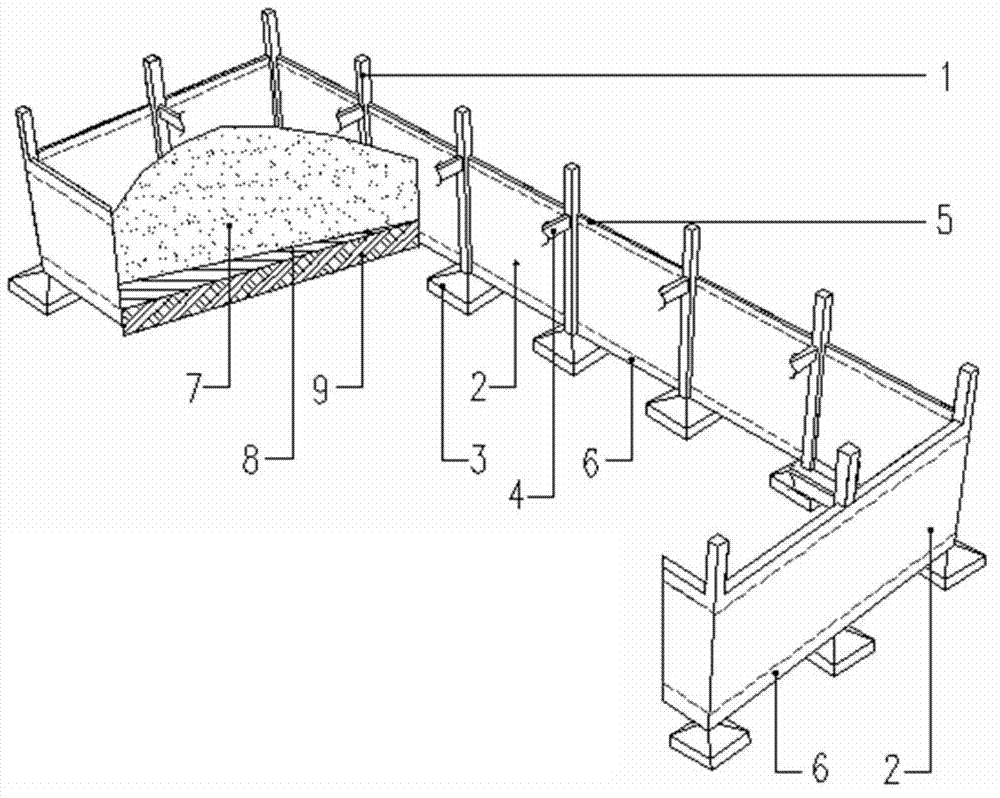
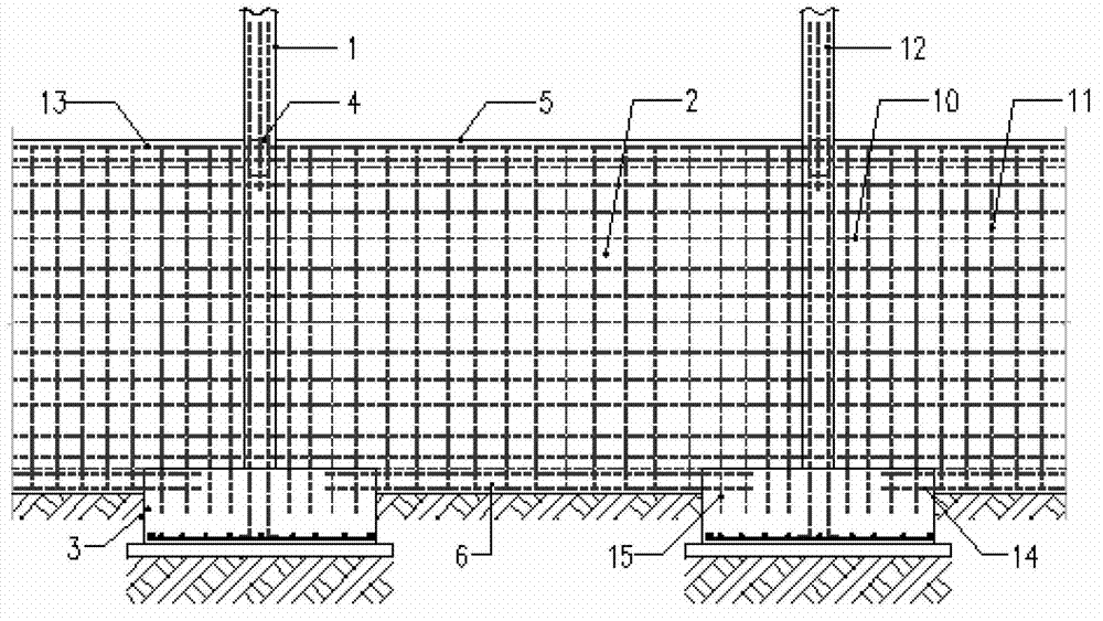
[0023] figure 1 It is a schematic diagram of the frame model of the combined force-bearing steel concrete retaining wall without foundation in this embodiment, figure 2 Schematic diagram of reinforcement configuration for the retaining wall.

[0024] like figure 1 and figure 2 As shown, the reinforced concrete retaining wall 2 is poured together with the frame column 1 of the reinforced concrete frame of the factory building. The upper concealed beam 5 and the lower concealed beam 6 are arranged inside the reinforced concrete retaining wall 2 , and the stressed steel bars 13 in the concealed beam penetrate through the frame column 1 in the horizontal direction. The frame foundation 3 is used to support the frame column 1 and is poured together with the lower hidden beam 6 . The horizontal stress bars 14 of the lower hidden beam 6 and the vertical stress...


PUM

PropertyMeasurementUnit
Thicknessaaaaaaaaaa

Abstract

The invention provides a combined stress foundation-less steel concrete retaining wall comprising a reinforced concrete retaining wall, upper hidden beams and lower hidden beams; the combined stress foundation-less steel concrete retaining wall is cast with the frame column of a factory steel concrete frame; vertical stress reinforcing steel bars in the wall are anchored in a frame foundation for supporting the frame column, and horizontal stress reinforcing steel bars of the wall penetrate through the frame column; the upper hidden beams are arranged on the upper ends in the reinforced concrete retaining wall and penetrate through the frame column; and the lower hidden beams are arranged on the lower ends in the reinforced concrete retaining wall, and the stress reinforcing steel bars of the lower hidden beams are anchored in the frame foundation. According to the combined stress foundation-less steel concrete retaining wall, the steel concrete retaining wall and a factory steel concrete frame are connected together, no retaining wall foundation is set so that the stress of the retaining wall and a frame system is combined, the effects of fully reducing the price and realizing attractive appearance are achieved, and the combined stress foundation-less steel concrete retaining wall is widely applied to various warehouse retaining walls in an industrial factory, and particularly applicable to the gypsum stockpile retaining walls in the desulfurization industry.

Description

technical field [0001] The invention relates to a retaining wall, in particular to a steel concrete retaining wall with combined force and no foundation, which is suitable for retaining walls of various warehouses in industrial workshops, and is especially suitable for retaining walls of gypsum warehouses in the desulfurization industry. Background technique [0002] Wet desulfurization is the flue gas SO 2 The main technology of treatment, gypsum is a main by-product of this process, and this by-product is generally transported to the gypsum warehouse through vacuum dehydration belts and conveyor belts in the process flow. The usual process arrangement is that the gypsum warehouse is set on the ground floor of the factory building, and the conveyor belt layer and the vacuum belt layer are arranged above the gypsum warehouse. The production of gypsum by-products in the wet desulfurization process is relatively large. Gypsum exists in the form of powder in the gypsum storage...

Claims


Application Information

Patent Timeline
IPC IPC(8): E04H7/26
Inventor 曹东申镇肖志均
Owner DATANG ENVIRONMENT IND GRP
Why Eureka
Try Eureka